
Surface modified unit cell lattice structures for optimized secure freeform fabrication

a technology of surface modified unit cells and lattice structures, applied in the direction of instruments, prostheses, manufacturing tools, etc., can solve the problems of additional steps, time, and potential site for the generation of debris, and the geometries of porous geometries are not supported by the underlying structur

Active Publication Date: 2015-11-10
HOWMEDICA OSTEONICS CORP +1
View PDF313 Cites 109 Cited by
  • Summary
  • Abstract
  • Description
  • Claims
  • Application Information

AI Technical Summary

Benefits of technology

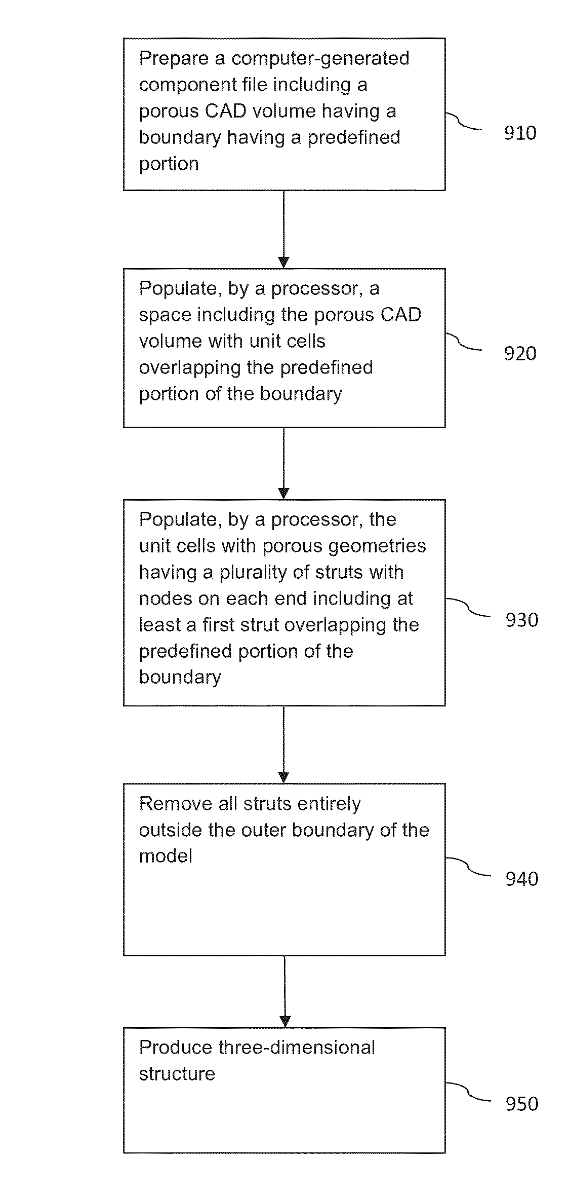
The patent describes a process for creating a computer-generated model of a three-dimensional structure made up of porous geometries. The process involves preparing a computer-generated component file with a porous CAD volume and a boundary, and then populating the space with unit cells that overlap the boundary. The unit cells are connected at nodes at the ends of struts that form the porous geometries. The process may also involve removing all struts outside the porous CAD volume and connecting the remaining struts at nodes at each end. The model can be produced by depositing metal powder onto a substrate and scanning a beam to form the physical layers of the structure. The model can also include an elongated fixation member for assembly or engagement with a mating structure. The technical effects of this patent include improved methods for creating computer-generated models of complex structures using porous geometries.

Problems solved by technology

Such truncation helps to achieve the near-net shape of the intended structure, but truncated or clipped struts may, in some instances, create a situation where the porous geometries are un-supported by the underlying structures.
These truncated struts may present a potential site for the generation of debris as protruding struts may fracture.
While bone cement may be used at the time of surgery to provide initial stability, the application of such requires additional steps, risks, and time, and may interfere with the intended bone ingrowth capabilities of the surface.
Over a long period of time, the cement acts as an additional mechanical structure but adds additional risks due to potential failure within the cement mantle and at both the cement-bone and cement-implant interfaces.

Method used


Image

  • Surface modified unit cell lattice structures for optimized secure freeform fabrication
  • Surface modified unit cell lattice structures for optimized secure freeform fabrication
  • Surface modified unit cell lattice structures for optimized secure freeform fabrication

Examples


Embodiment Construction

[0053]This invention relates generally to generating computer models of three-dimensional structures. These models may be used to prepare porous tissue in-growth structures in medical implants and prostheses. The models may include features corresponding to tangible structures having nodes along a predefined outer boundary.

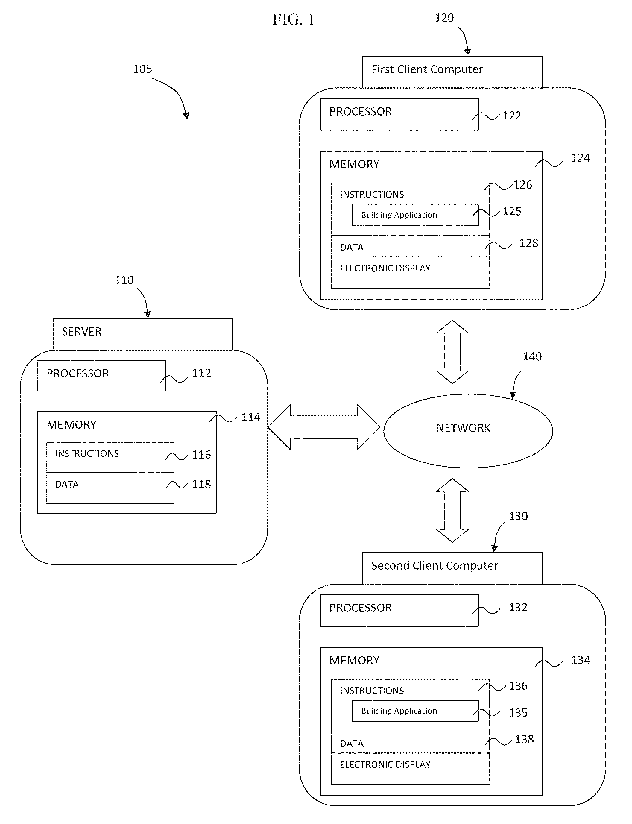
[0054]FIG. 1 depicts a system 105 that may be used, among other functions, to generate, store and share three-dimensional models of structures. The system 105 may include at least one server computer 110, a first client computer 120, and in some instances, at least a second client computer 130. These computers may send and receive information via a network 140. For example, a first user may generate a model at the first client device 120. The model may then be uploaded to the server 110 and distributed via the network 140 to the second client computer 130 for viewing and modification by at least a second user.

[0055]The network 140, and intervening communication po...


PUM

PropertyMeasurementUnit
angleaaaaaaaaaa
angleaaaaaaaaaa
lengthsaaaaaaaaaa

Abstract

Aspects of the present disclosure relate generally to preparing models of three-dimensional structures. In particular, a model of a three-dimensional structure constructed of porous geometries is prepared. A component file including a porous CAD volume having a boundary is prepared. A space including the porous CAD volume is populated with unit cells. The unit cells are populated with porous geometries having a plurality of struts having nodes on each end. The space is populated with at least one elongated fixation element extending beyond the boundary to produce an interlocking feature enabling assembly or engagement with a mating structure.

Description

CROSS-REFERENCE TO RELATED APPLICATIONS[0001]The present application is a continuation-in-part of U.S. patent application Ser. No. 13 / 441,154, filed Apr. 6, 2012, the disclosure of which is incorporated herein by reference.FIELD OF THE INVENTION[0002]The present invention relates generally to preparing computer-generated models of porous structures. In particular, the surfaces of computer-generated models of structures may be modified through movement and removal of struts and nodes of porous geometries near the surface to produce surfaces conforming to the surfaces of intended physical structures being modeled.BACKGROUND OF THE INVENTION[0003]The field of free-form fabrication has seen many important recent advances in the fabrication of articles directly from computer controlled databases. These advances, many of which are in the field of rapid prototyping of articles such as prototype parts and mold dies, have greatly reduced the time and expense required to fabricate articles, p...

Claims


Application Information

Patent Timeline
Patent Type & Authority Patents(United States)
IPC IPC(8): G06F17/50B22F3/105A61F2/28
CPCA61F2/28B22F3/1055G06F17/50A61F2/30767B33Y80/00A61F2/30942A61F2002/30952G06F30/00Y02P10/25B22F10/28B22F10/80B33Y50/00B23K26/342B23K15/0086
Inventor DONG, NICHOLAS NAI GUANGPOGGIE, MATTHEW P.KLEIN, ROBERT W.JONES, ERICSUTCLIFFE, CHRISTOPHER J.ROBINSON, JOEJONES, DANMULLEN, LEWISSTAMP, ROBIN
Owner HOWMEDICA OSTEONICS CORP
Learn More