Filter manufacturing apparatus and filter manufacturing method

a filter manufacturing and filter technology, applied in the direction of printing, typewriters, other printing apparatus, etc., can solve the problems of time-consuming adjustment and complicated control, and achieve the effect of efficient diffuser, reduced pitch unevenness, and reduced pitch unevenness

Active Publication Date: 2015-11-10
DAINIPPON SCREEN MTG CO LTD
View PDF5 Cites 2 Cited by
  • Summary
  • Abstract
  • Description
  • Claims
  • Application Information

AI Technical Summary

Benefits of technology

[0009]According to the invention described above, printing cells having an equal number of dot areas in the direction perpendicular to the transport direction of the printing material are set based on a filter pitch and a head resolution. Shift amounts between the filter pitch and the printing cells, and whether shift amounts of the printing cells exceed a unit dot area is determined. For the printing cells including shift amounts exceeding the unit dots area, the shift amounts are complemented by adjusting the number of dot areas included in the printing cells. Consequently, even if the filter pitch and head resolution are not in agreement, shifts of the filter pitch can be made smaller than the head resolution. Filters can be manufactured with high filter pitch accuracy by inkjet printing without inclining inkjet heads.
[0023]In a preferred example of the filter manufacturing method, the printing pattern has ejection dot areas on diagonal lines in the printing cells. With this method, the printing pattern has ejection dot areas on diagonal lines in the printing cells, which enables ejected ink to be efficiently diffused within the printing cells.

Problems solved by technology

However, this requires numerous steps such as mask baking, cleaning and chemical treatment for each filter color.
However, the conventional example with such construction has the following problems.
In this case, it is necessary to adjust printing timing of each nozzle individually, which makes control complicated.
An angle of inclination of the inkjet head must be changed whenever the filter pitch of a printing medium is changed, which requires a time-consuming adjustment.

Method used


Image

  • Filter manufacturing apparatus and filter manufacturing method
  • Filter manufacturing apparatus and filter manufacturing method
  • Filter manufacturing apparatus and filter manufacturing method

Examples


Embodiment Construction

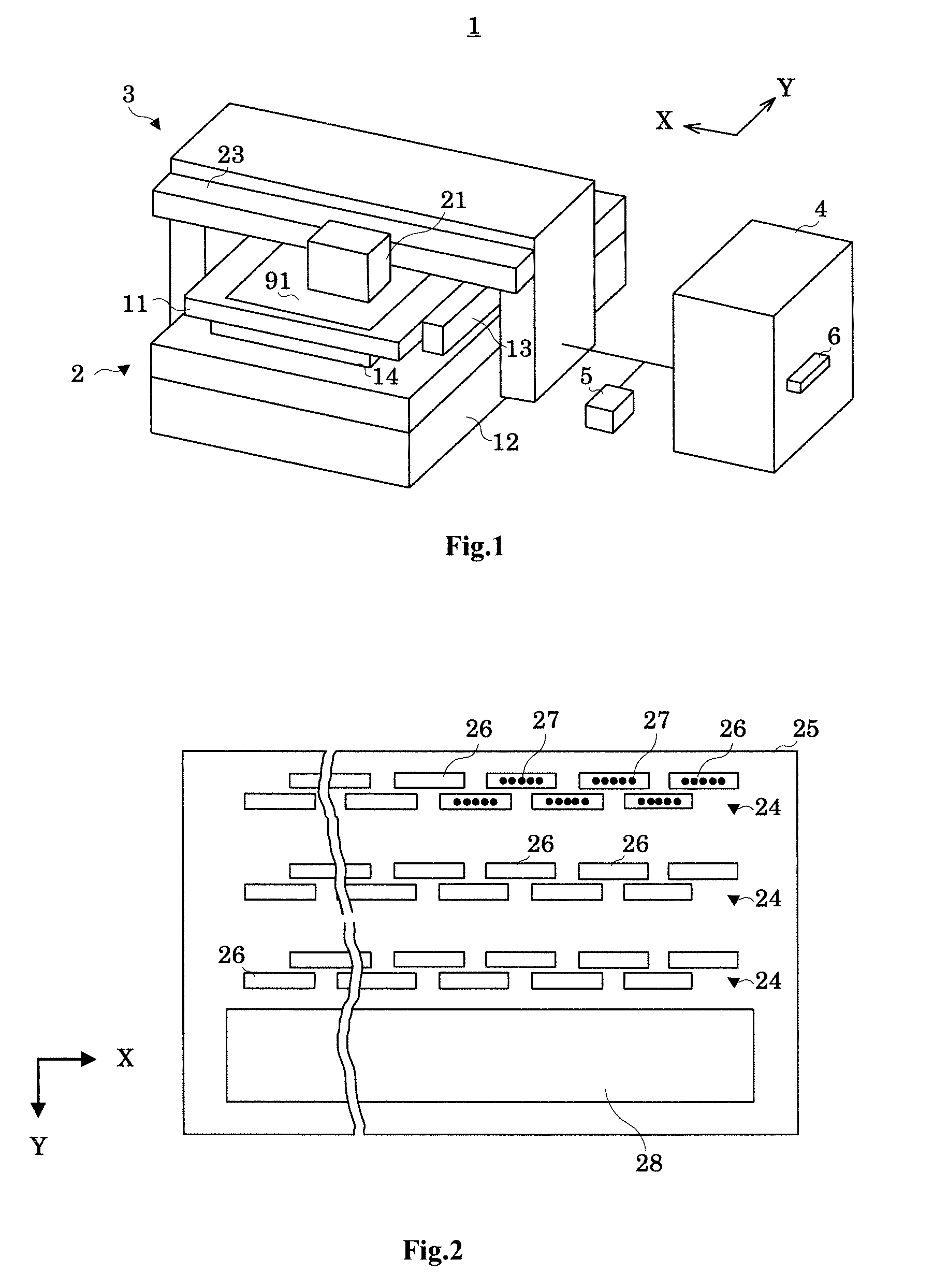
[0040]Embodiments of this invention will be described hereinafter with reference to the drawings. FIG. 1 is an overall outline view of a filter manufacturing apparatus.

[0041]1. Filter Manufacturing Apparatus

[0042]A filter manufacturing apparatus 1 manufactures color filters on a base material 91 by inkjet printing. This embodiment employs and describes an inkjet printing machine of the multipass type. The base material 91 may be a glass substrate, or may be paper with a coating agent applied thereto. The base material 91 corresponds to the printing medium in this invention.

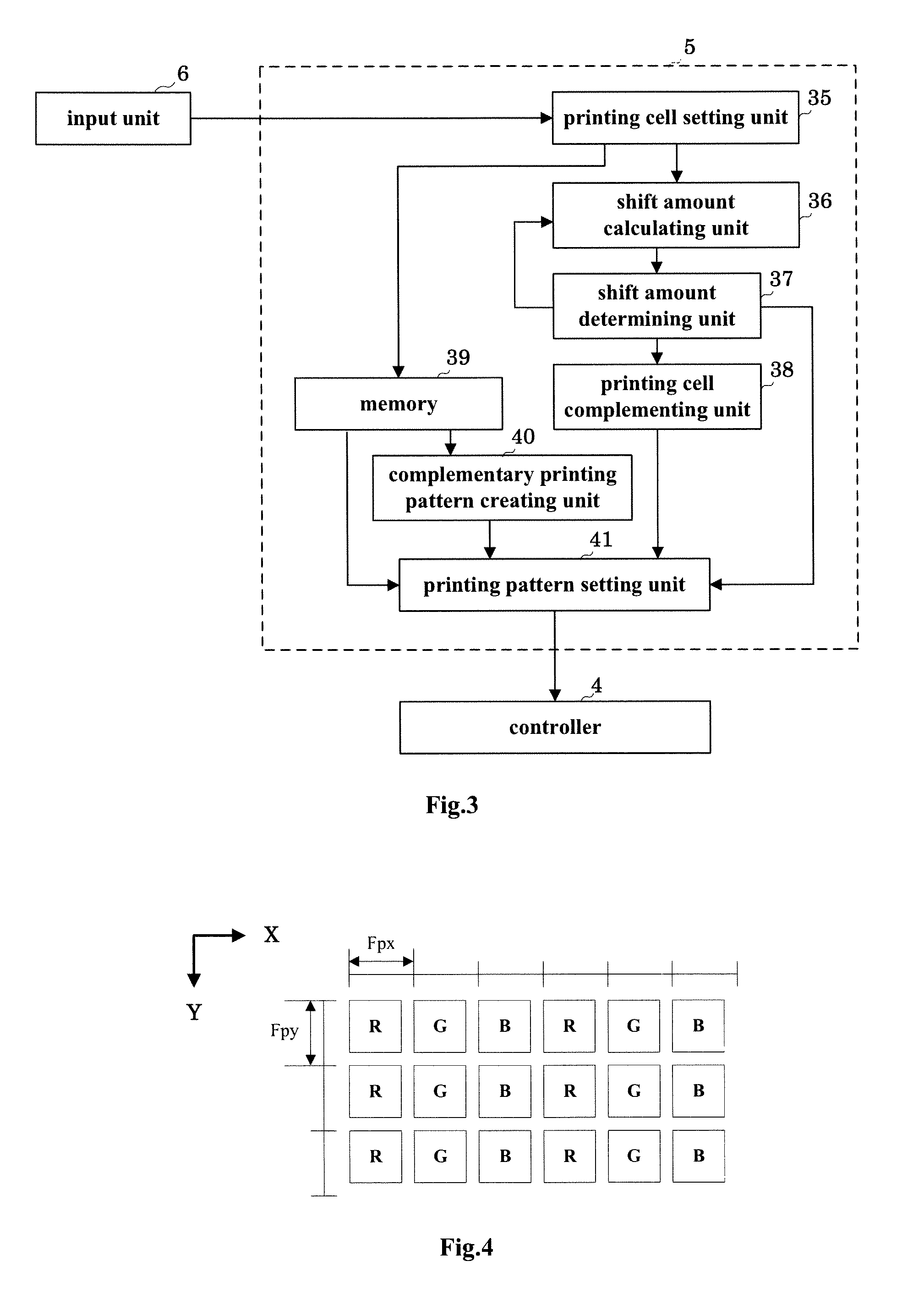
[0043]The filter manufacturing apparatus 1 includes a transport mechanism 2 for transporting the base material 91, a print head 3 for ejecting UV curable inks onto the base material 91 being transported, a controller 4 for controlling transport timing of the base material 91 and ink ejection timing of the print head 3, and an image data creator 5 for creating image data corresponding to areas to which inks are eje...


PUM


Abstract

A filter manufacturing apparatus includes a printing cell setting unit that sets, based on a predetermined filter pitch and a head resolution, printing cells having an equal number of dot areas in the direction perpendicular to the transport direction of the printing medium, a shift amount calculating unit that calculates shift amounts between the filter pitch and the printing cells in the direction perpendicular to the transport direction of the printing medium, a shift amount determining unit that determines whether shift amounts of the printing cells exceed a unit dot area; and a printing cell complementing unit that complements the shift amounts of the printing cells exceeding the unit dot area by adjusting the number of dot areas included in the printing cells.

Description

BACKGROUND OF THE INVENTION[0001](1) Field of the Invention[0002]This invention relates to a filter manufacturing apparatus and a filter manufacturing method, and more particularly to a technique of manufacturing color filters by inkjet printing for use in liquid crystal displays or electronic paper.[0003](2) Description of the Related Art[0004]Conventionally, there is a manufacturing method by photolithography as a method of manufacturing liquid crystal color filters. Manufacturing color filters by photolithography can provide filters with high quality in positional precision. However, this requires numerous steps such as mask baking, cleaning and chemical treatment for each filter color.[0005]So, research has been made on a method of manufacturing color filters by inkjet printing in recent years. Compared with photolithography, inkjet printing can reduce manufacturing steps and can manufacture filters at low cost. Patent Document 1 (Japanese Unexamined Patent Publication H9-138306...

Claims


Application Information

Patent Timeline
Patent Type & Authority Patents(United States)
IPC IPC(8): B41J3/407B41J2/045
CPCB41J3/407B41J2/04505B41J2/04573B41J2/04586
Inventor KAWABATA, MOTONOBUKAWADA, TORUKIBUNE, KAZUSHIYAMAMOTO, TAKAHARU
Owner DAINIPPON SCREEN MTG CO LTD
Why Eureka
Try Eureka