Method and apparatus for exposing optical disk master

a technology of optical disks and masters, applied in the field of methods and apparatus for exposing optical disk masters, can solve the problems of difficult tracking servo operation, prone to deviation from its proper operation, sharp decrease of push-pull tracking error signals, etc., and achieve the effect of improving track pitch accuracy

Inactive Publication Date: 2005-05-17
PANASONIC CORP
View PDF2 Cites 1 Cited by
  • Summary
  • Abstract
  • Description
  • Claims
  • Application Information

AI Technical Summary

Benefits of technology

[0014]Therefore, with the foregoing in mind, it is an object of the present invention to provide a method and app

Problems solved by technology

Therefore, when the track pitch becomes narrower as described above, the push-pull tracking error signal decreases sharply.
This makes it difficult to perform tracking servo.
Even if the tracking servo is performed, it is prone to deviate from its proper operation.
Moreover, there is also a limit to the track pitch ac

Method used


Image

  • Method and apparatus for exposing optical disk master
  • Method and apparatus for exposing optical disk master
  • Method and apparatus for exposing optical disk master

Examples


embodiment 1

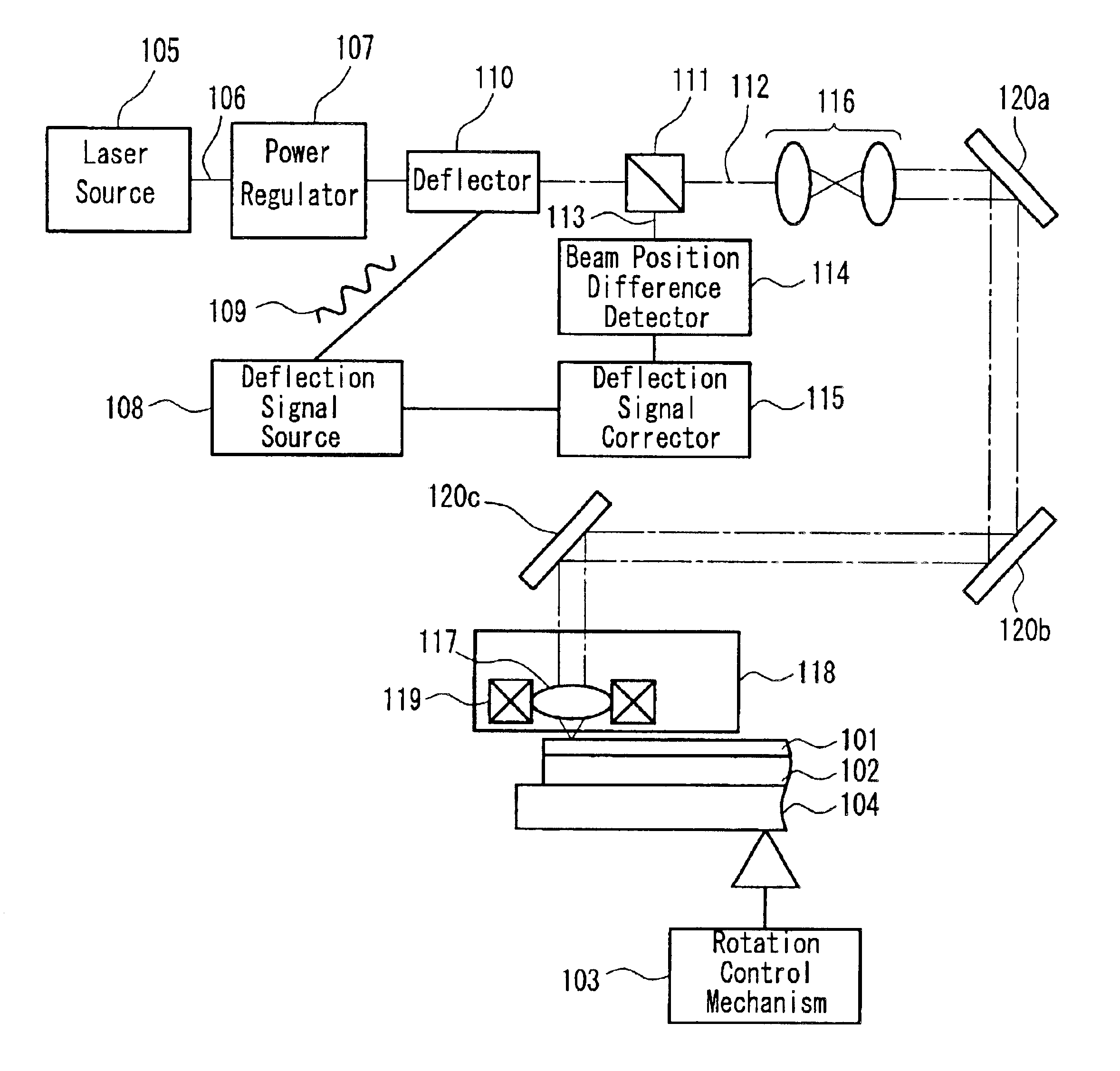
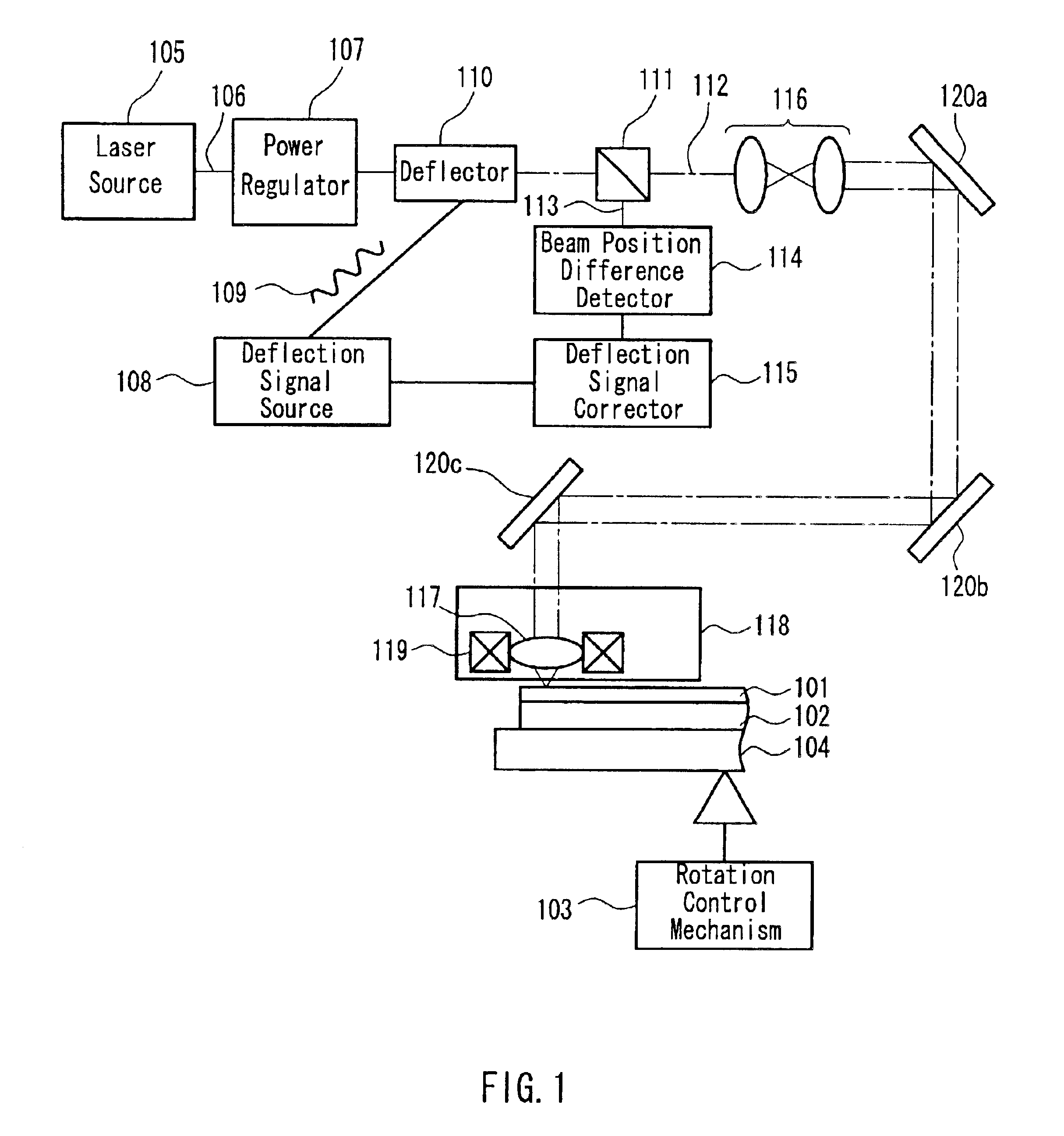
[0040]FIG. 1 is a block diagram showing an optical disk master exposing apparatus of Embodiment 1. This embodiment describes the optical disk master exposing apparatus using a laser beam.

[0041]In the exposing apparatus illustrated in FIG. 1, a turntable 104 for supporting a substrate disk 102, a transfer mechanism 118 for driving an objective lens 117, and a focusing control mechanism 119 are the same as those in FIG. 8. The configuration of an optical system that includes a laser source 105, a power regulator 107, a deflector 110, and an expander 116 also is the same. Therefore, the elements related to the conventional example are denoted by the same reference numerals, and the explanation of each element will not be repeated.

[0042]The exposing apparatus further includes a beam splitter 111 that divides a laser beam 106 transmitted by the deflector 110 into a first laser beam 112 and a second laser beam 113. Like the conventional example, the first laser beam 112 is incident on the...

embodiment 2

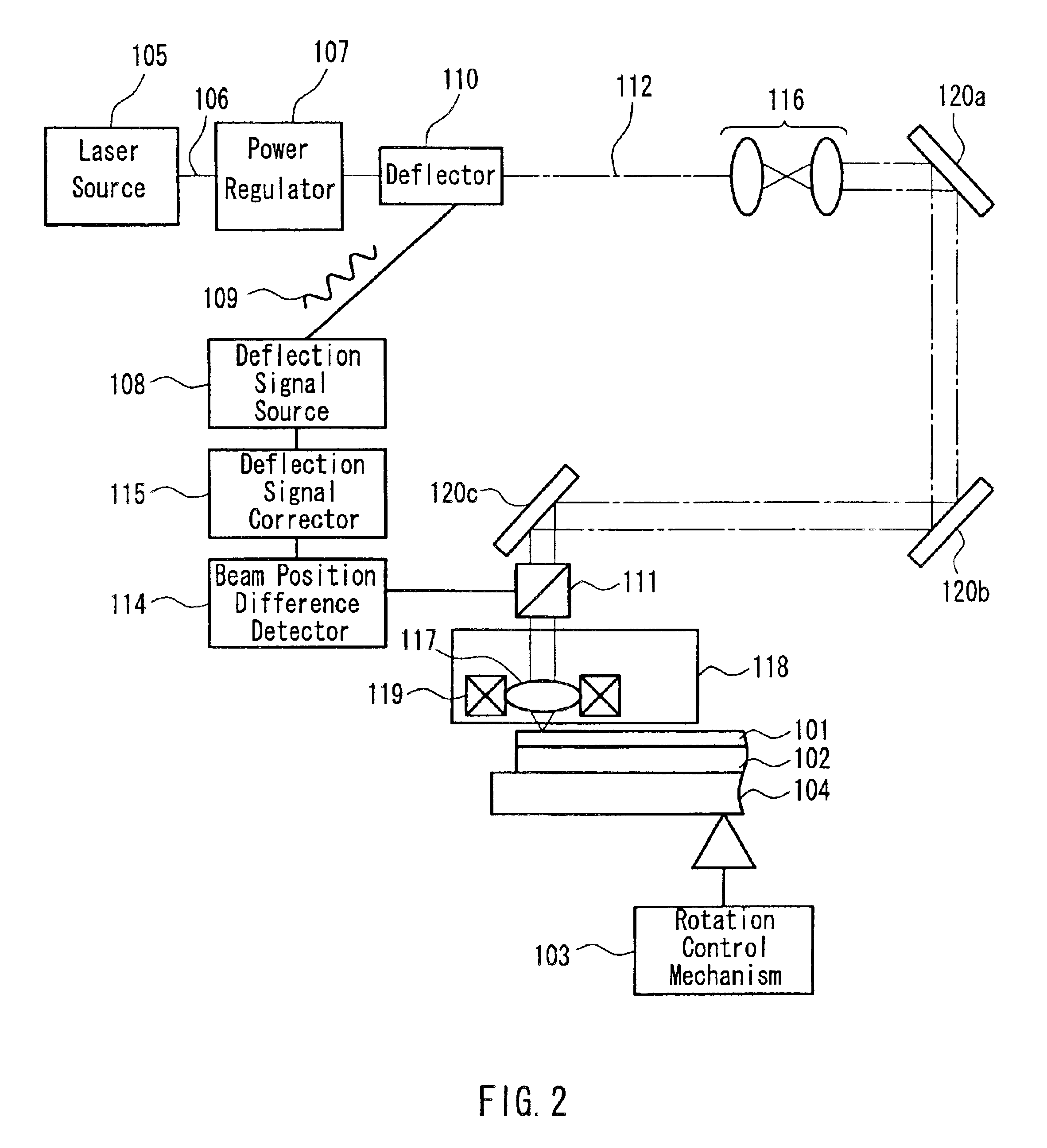
[0053]FIG. 3 is a block diagram showing an optical disk master exposing apparatus of Embodiment 2. This embodiment differs from Embodiment 1 in that the track pitch accuracy is improved by correcting the displacement component caused by a mechanical structure instead of that caused by the fluctuation of a laser beam.

[0054]In the exposing apparatus illustrated in FIG. 3, a turntable 104 for supporting a substrate disk 102 and a focusing control mechanism 119 for driving an objective lens 117 are the same as those in FIG. 8. The configuration of an optical system that includes a laser source 105, a power regulator 107, a deflector 110, and an expander 116 also is the same. Therefore, the elements related to the conventional example are denoted by the same reference numerals, and the explanation of each element will not be repeated.

[0055]In this apparatus, a deflection signal 109 output from a deflection signal source 108 is corrected by a center distance difference detector 202 and a ...

embodiment 3

[0066]FIG. 5 is a block diagram showing an optical disk master exposing apparatus of Embodiment 3. This exposing apparatus is formed of the same combination of elements as that shown in FIG. 8. Therefore, the elements related to the conventional example are denoted by the same reference numerals, and the explanation of each element will not be repeated.

[0067]In this embodiment, a far ultraviolet laser source 105 is used, and an electrooptical element is used as a deflector 301 instead of a conventional acoustooptical element.

[0068]The deflector including a conventional acoustooptical element causes drive-frequency fluctuations. This makes the deflection direction unstable, and a laser beam emitted from the deflector fluctuates, resulting in degradation of the track pitch accuracy. The laser beam fluctuation increases with a decrease in track pitch, which in turn increases fluctuations in the push-pull tracking error signal. In the deflector 301 that utilizes the electrooptical effec...


PUM


Abstract

A method for exposing an optical disk master includes rotating a substrate disk coated with a photoresist, focusing a beam on the photoresist for exposure through an objective lens, and exposing the photoresist so as to form tracks on the substrate disk in its circumferential direction. At this time, the beam is deflected at least temporarily by passing through a deflector. The beam is divided into a first beam and a second beam after passing through the deflector, and the first beam is focused on the photoresist. A difference between the current position and the target position of an optical path of the second beam is detected, and the deflection operation of the deflector is corrected based on the difference so that the optical path of the second beam is located at the target position. This method can improve the track pitch accuracy of an optical disk having a narrow track pitch.

Description

BACKGROUND OF THE INVENTION[0001]1. Field of the Invention[0002]The present invention relates to a method and apparatus for exposing an optical disk master.[0003]2. Description of the Related Art[0004]With a growing amount of information needed for information processing equipment and image / acoustic equipment, optical disks have attracted considerable attention in recent years because they are excellent in easy data access, mass storage, and miniaturization of the equipment. There are three types of optical disks: read-only type, write-once type, and recording / reproducing type. Examples of the recording / reproducing type include a phase change optical disk and a magneto-optical disk. These disks are called CD, DVD, MO, or the like and are used in various applications.[0005]For a read-only optical disk, embossed pit trains are formed in spiral fashion, and information is reproduced by irradiating these pit trains with reproduction light and detecting the presence or absence of a pit a...

Claims


Application Information

Patent Timeline
IPC IPC(8): G11B7/00G11B7/095G11B7/007G11B7/085G11B7/09G11B7/125G11B7/26
CPCG11B7/261G11B7/128G11B7/08547G11B7/0901G11B7/24079
Inventor SATO, SHUJIABE, SHINYATOMIYAMA, MORIOTSUKUDA, MASAHIKOITO, EIICHI
Owner PANASONIC CORP
Why Eureka
Try Eureka