Endoscopic high-frequency hemostatic forceps

a high-frequency, hemostatic technology, applied in the field of endoscopic high-frequency hemostatic forceps, can solve the problems of unnecessary tissue destruction, bleeding or perforation, etc., and achieve the effect of high-frequency hemostatic treatment, safe and fas

Active Publication Date: 2015-11-17
KANEKA CORP +1
View PDF25 Cites 193 Cited by
  • Summary
  • Abstract
  • Description
  • Claims
  • Application Information

AI Technical Summary

Benefits of technology

[0004]Employing the high-frequency treatment instrument that includes the pair of forceps cups serving as high-frequency electrodes according to the patented document 1 allows the area of the high-frequency electrode brought into contact with the biological tissue to be substantially reduced, and the biological tissue pinched by the pair of forceps cups to be securely fixed therebetween. Accordingly, the high-frequency cauterization can be performed as desired on a target part. However, in the forceps type high-frequency treatment instrument according to the patented document 1, the entire outer periphery of the closing-side surface of the forceps cups, which contacts the biological tissue, constitutes an exposed metal surface. Here, the temperature of a biological tissue increases in proportion to a square of the current density of the high-frequency current, and therefore the biological tissue is not heated such that the hemostatic effect is instantaneously attained. This is because the high-frequency treatment instrument according to the patented document 1 is not intended for hemostasis but for collecting a tissue by resection from an organism. Accordingly, employing the forceps type high-frequency treatment instrument according to the patented document 1 for a hemostatic treatment may cause a deep burn as schematically illustrated in FIG. 11, in the biological tissue contacted by an exposed metal portion 100a of a forceps cup 100 thereby incurring unnecessary tissue destruction, which may result in bleeding or perforation several days later.
[0005]The present invention has been accomplished in view of the foregoing problem, with an object to provide an endoscopic high-frequency hemostatic forceps that allows a hemostatic treatment by a high-frequency current to be safely and quickly performed without causing a deep burn in the biological tissue.
[0012]The pair of forceps elements may each include the sawtooth portion formed on the respective closing-side surfaces, and the pair of forceps elements electrically connected to each other and serves as a monopolar high-frequency electrode. With such a configuration, the hemostatic treatment can be as safely performed as in the case of employing a bipolar high-frequency electrode.
[0013]Thus, the endoscopic high-frequency hemostatic forceps according to the present invention includes the sawtooth portion having a plurality of concavo-convex structures which constitute a sawtooth-shape formed on the closing-side surface of the forceps element, and the bottom portion of the sawtooth-shape of the sawtooth portion is provided with the electrically insulative coating while the top portion of the sawtooth-shape of the sawtooth portion is made conductive. Such a configuration allows a biological tissue brought into contact with the top portion to be instantaneously cauterized at a high temperature, thereby enabling a high-frequency hemostatic treatment to be safely and quickly performed without causing a deep burn in the biological tissue.

Problems solved by technology

Accordingly, employing the forceps type high-frequency treatment instrument according to the patented document 1 for a hemostatic treatment may cause a deep burn as schematically illustrated in FIG. 11, in the biological tissue contacted by an exposed metal portion 100a of a forceps cup 100 thereby incurring unnecessary tissue destruction, which may result in bleeding or perforation several days later.

Method used


Image

  • Endoscopic high-frequency hemostatic forceps
  • Endoscopic high-frequency hemostatic forceps
  • Endoscopic high-frequency hemostatic forceps

Examples


first embodiment

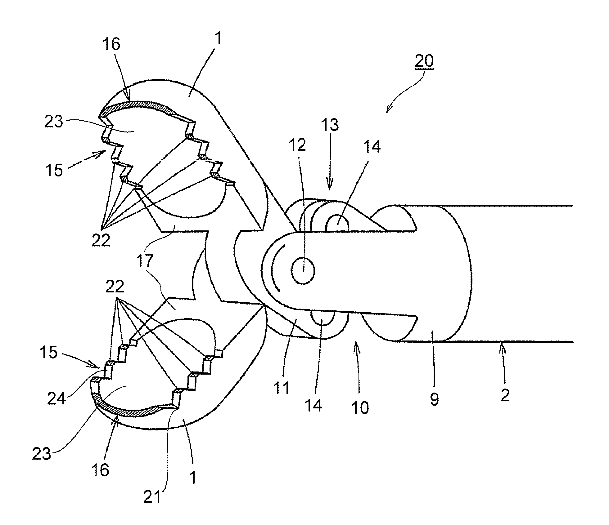
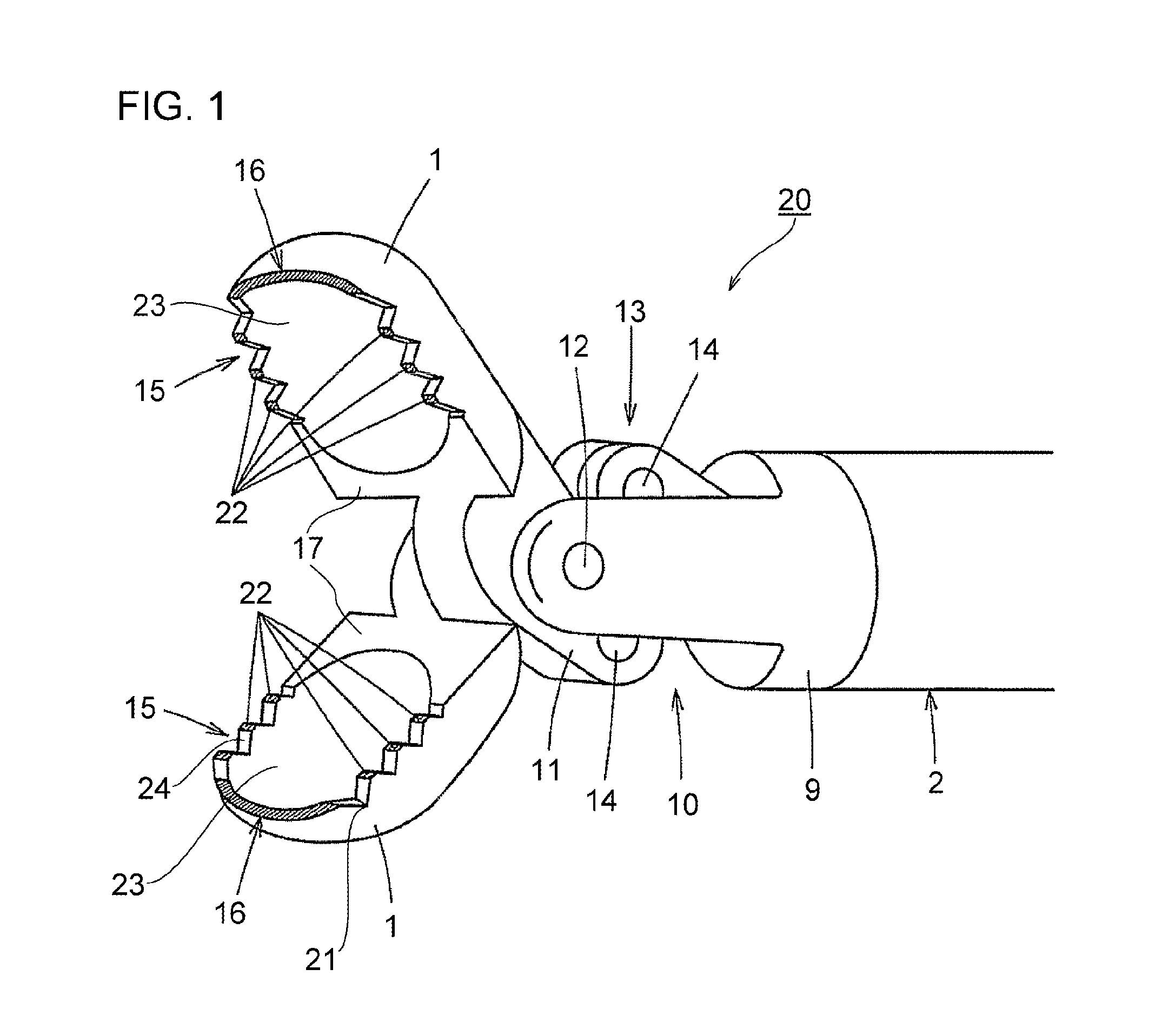
[0027]FIG. 1 is a perspective view showing a distal portion of an endoscopic high-frequency hemostatic forceps (hemostatic forceps 20) according to the present invention.

[0028]First, a general description of the hemostatic forceps 20 according to this embodiment will be given.

[0029]The hemostatic forceps 20 includes a pair of forceps elements (forceps cups 1) constituted of a conductive metal so as to serve as a high-frequency electrode, and configured to be able to freely change into a state where front portions of the pair of forceps elements are open, and a state where the pair of forceps elements are close.

[0030]A sawtooth portion 15 having a plurality of concavo-convex structures which constitute a sawtooth-shape is provided on at least one of opposing closing-side surfaces 17 of the pair of forceps cups 1. A bottom portion 21 of the sawtooth-shape of the sawtooth portion 15 is provided with an electrically insulative coating, while a top portion 22 of the sawtooth-shape of the...

second embodiment

[0061]FIG. 6 shows a distal portion of the hemostatic forceps 20 according to the present invention. In this embodiment, the sawtooth portion 15 are provided on the front edge portion 16 of the outer periphery 18 of the respective closing-side surfaces 17 of the pair of forceps cups 1, in addition to the side edge portions 19.

[0062]Each of the sawtooth portion 15 is provided with the electrically insulative coating over its entirety except for the respective top portions 22, and hence the exposed metal surface 15a where the conductive metal is exposed is formed only in the top portions 22 of the sawtooth portion 15. The configuration of the remaining portion is the same as that of the first embodiment. Forming thus the sawtooth portion 15 on the front edge portion 16 and the respective side edge portions 19 of the closing-side surface 17 of the forceps cup 1 leaving only the top portions 22 as the exposed metal surface 15a enables the hemostatic treatment to be performed even more q...

fifth embodiment

[0070]FIG. 10 is a perspective view showing a distal portion of the hemostatic forceps 20 according to the present invention.

[0071]In the hemostatic forceps 20 according to this embodiment, the pair of forceps cups (forceps elements) 1 each includes the opening 23 on the respective closing-side surface 17, as in the first embodiment. However, a difference from the first embodiment lies in that the inner surface of the opening 23 is not provided with the electrically insulative coating, and is hence conductive.

[0072]In this embodiment, the conductive metal constituting the forceps cup 1 is exposed in the top portions 22 (exposed metal surfaces 15a) of the sawtooth portion 15, the exposed metal surface 16a of the front edge portion 16, and in the inner surface of the opening 23. Such a configuration allows a high-frequency current to be supplied also to a portion of the biological tissue in contact with the inner surface of the opening 23. Therefore, the configuration according to thi...


PUM


Abstract

A hemostatic forceps (20) includes a pair of forceps elements (forceps cups (1)) constituted of a conductive metal and configured to serve as high-frequency electrodes and configured to be able to change into a state where front portions of the pair of forceps cups (1) are open, and a state where the pair of forceps cups (1) are close. A sawtooth portion (15) having a plurality of concavo-convex structures which constitute a sawtooth-shape is provided on at least one of respective closing-side surfaces (17) of the pair of forceps cups (1). The sawtooth portion (15) is provided with an electrically insulative coating over its bottom portion (21), but not on a top portion (22) thereof, and hence the top portion (22) is conductive.

Description

TECHNICAL FIELD[0001]The present invention relates to an endoscopic high-frequency hemostatic forceps applicable to hemostasis of a biological tissue.BACKGROUND ART[0002]An endoscopic hemostatic forceps is utilized to apply a high-frequency current to a pair of high-frequency electrodes pinching a biological tissue therebetween to thereby coagulate the biological tissue by cauterization. In the case where the high-frequency electrodes contacting the biological tissue have a large area, it takes a long time before the contact portion is sufficiently heated for attaining a hemostatic effect. In this case, the biological tissue suffers a deep burn therein over an extensive area thus suffering unnecessary tissue destruction, while the hemostatic effect, which is the object of the treatment, cannot be attained as desired. Accordingly, a forceps type high-frequency treatment instrument has been proposed that includes a pair of forceps cups constituted of a conductive metal that serves as ...

Claims


Application Information

Patent Timeline
Patent Type & Authority Patents(United States)
IPC IPC(8): A61B18/14A61B18/00A61B17/29
CPCA61B18/1445A61B18/1442A61B17/29A61B2018/00083A61B2018/00589A61B2018/00595
Inventor NISHIMURA, MAKOTONISHIMURA, MIYUKI
Owner KANEKA CORP
Why Eureka
Try Eureka