Particle beam device having a sample holder

a sample holder and beam device technology, applied in the direction of material analysis using wave/particle radiation, instruments, nuclear engineering, etc., can solve the problems of complex alignment by hand, time-consuming procedure, and inability to carry out plurality analysis, etc., to achieve the effect of increasing flexibility and time-consuming procedur

Active Publication Date: 2015-11-17
CARL ZEISS MICROSCOPY GMBH
View PDF19 Cites 0 Cited by
  • Summary
  • Abstract
  • Description
  • Claims
  • Application Information

AI Technical Summary

Benefits of technology

[0018]An advantage of the system described herein is that an additional degree of freedom is created by the rotation of the first sample holding device relative to the sample holder about the third axis of rotation, and so a first sample arranged on the first sample holding device can be positioned sufficiently well with respect to the first particle beam for the purpose of an analysis and / or treating. In principle, the system described herein allows an increase in the flexibility when positioning the first sample with respect to the first particle beam. More particularly, it is ensured that the first sample can in principle be aligned relative to the first optical axis by a rotation of the sample holder about the second axis of rotation. Thereupon it is possible to undertake a fine adjustment of the position of the first sample in respect of the first optical axis and / or an alignment of the first sample with respect to the raster area of the first particle beam column by rotating the first sample holding device about the third axis of rotation.
[0019]In particular, the system described herein is also advantageous when the particle beam device is used to carry out a method in which a different alignment of the first sample is required. By way of example, this is envisaged in the production of a plurality of TEM lamellae, which should be prepared from a sample and should in each case have a different orientation. In this case, it is not necessary during the production of such TEM lamellae for the first sample holding device with the first sample to be detached a number of times from the sample holder and for the first sample holding device to be reattached to the sample holder, with a realignment of the first sample being carried out in the process. In the aforementioned case, provision is made for the sample chamber firstly to be ventilated, the first sample holding device to be detached and to be newly aligned, and for the sample chamber to be pumped out again in order to generate a vacuum. This time-consuming procedure is avoided in the case of the system described herein.
[0028]The use of a plurality of sample holding devices, which are arranged on the sample holder, is advantageous in the case of the system described herein. The system described herein then firstly allows a sample to be interchanged without having to remove the sample holder or one of the sample holding devices from the sample chamber. Secondly, the risk of a collision of one of the sample holding devices with a component of the particle beam device is avoided. By way of example, if the plurality of sample holding devices are arranged on the sample holder in a circular fashion, a first rotation of the sample holder about the second axis of rotation may for example bring about a sample interchange. Expressed differently, the first sample holding device or the second sample holding device with a sample to be analyzed is brought into a particular relative position with respect to the first optical axis. Subsequently, a rotation of the first sample holding device about the third axis of rotation or a rotation of the second sample holding device about the fourth axis of rotation brings about a relatively quick alignment of the first sample or the second sample with respect to the raster area of the first particle beam column. At the same time, the risk of the sample holder or the first sample holding device or second sample holding device striking components of the particle beam device is reduced.
[0032]In a further embodiment of the particle beam device according to the system described herein, provision is additionally or alternatively made for the control apparatus to be connected to both the first movement apparatus and the second movement apparatus. In a further embodiment in turn, provision is additionally or alternatively made for at least one of the connections between the control apparatus and one of the two movement apparatuses to be embodied e.g. mechanically, electronically and / or optically. The aforementioned embodiments allow the control apparatus to be used to control firstly the rotation of the first sample holding device about the third axis of rotation. Secondly, the control apparatus can control the rotation of the second sample holding device about the fourth axis of rotation. Reference is explicitly made to the fact that the system described herein is not restricted to this and that the number of control apparatuses may be selected in a suitable fashion. Thus, in one alternative embodiment provision is made for the rotation of the first sample holding device to be controlled by a first control apparatus and the rotation of the second sample holding device to be controlled by a second control apparatus.
[0053]In one embodiment of the sample receptacle apparatus according to the system described herein, provision is made for the control apparatus to be connected to both the first movement apparatus and the second movement apparatus. In a further embodiment in turn, provision is made, in the process, for at least one of the connections between the control apparatus and one of the two movement apparatuses to be embodied e.g. mechanically, electronically and / or optically. The aforementioned embodiments allow the control apparatus to be used to control firstly the rotation of the first sample holding device about the third axis of rotation. Secondly, the control apparatus can control the rotation of the second sample holding device about the fourth axis of rotation.

Problems solved by technology

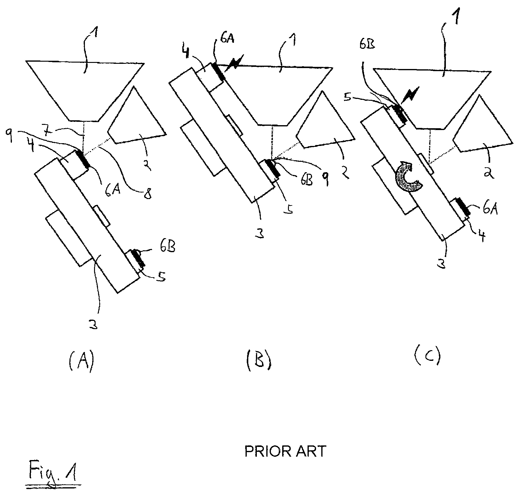
However, it is quite possible that during the eucentric movement of the sample holder parts of the sample holder collide with units of the particle beam device, which are arranged in a sample chamber of the particle beam device with the sample holder.
However, the alignment by hand is complicated.
Moreover, such an alignment is often inaccurate.
Accordingly, carrying out an analysis of a plurality of samples, which are arranged on the sample holder by the sample holding devices, may be time-consuming and inaccurate.

Method used


Image

  • Particle beam device having a sample holder
  • Particle beam device having a sample holder
  • Particle beam device having a sample holder

Examples


Embodiment Construction

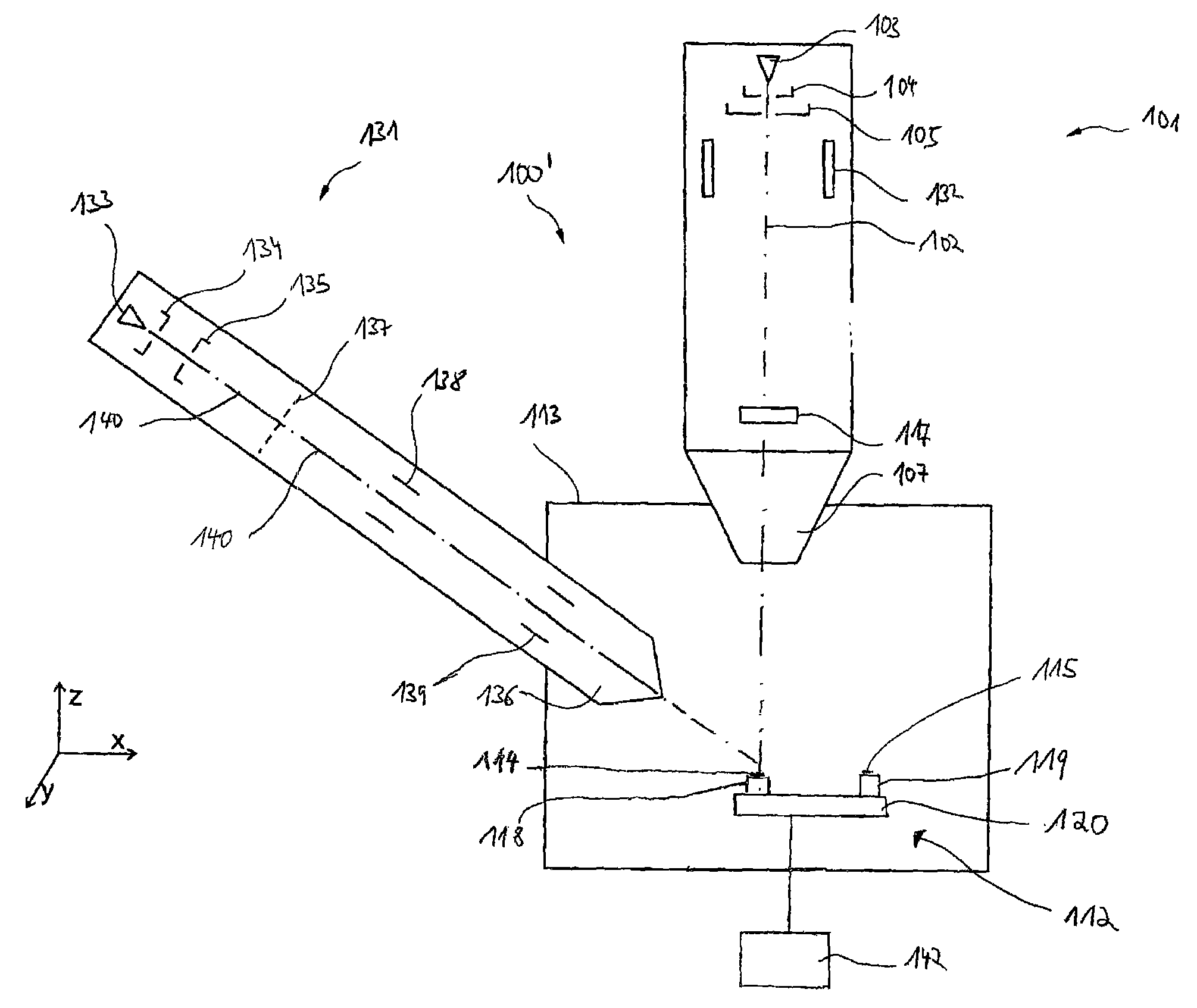
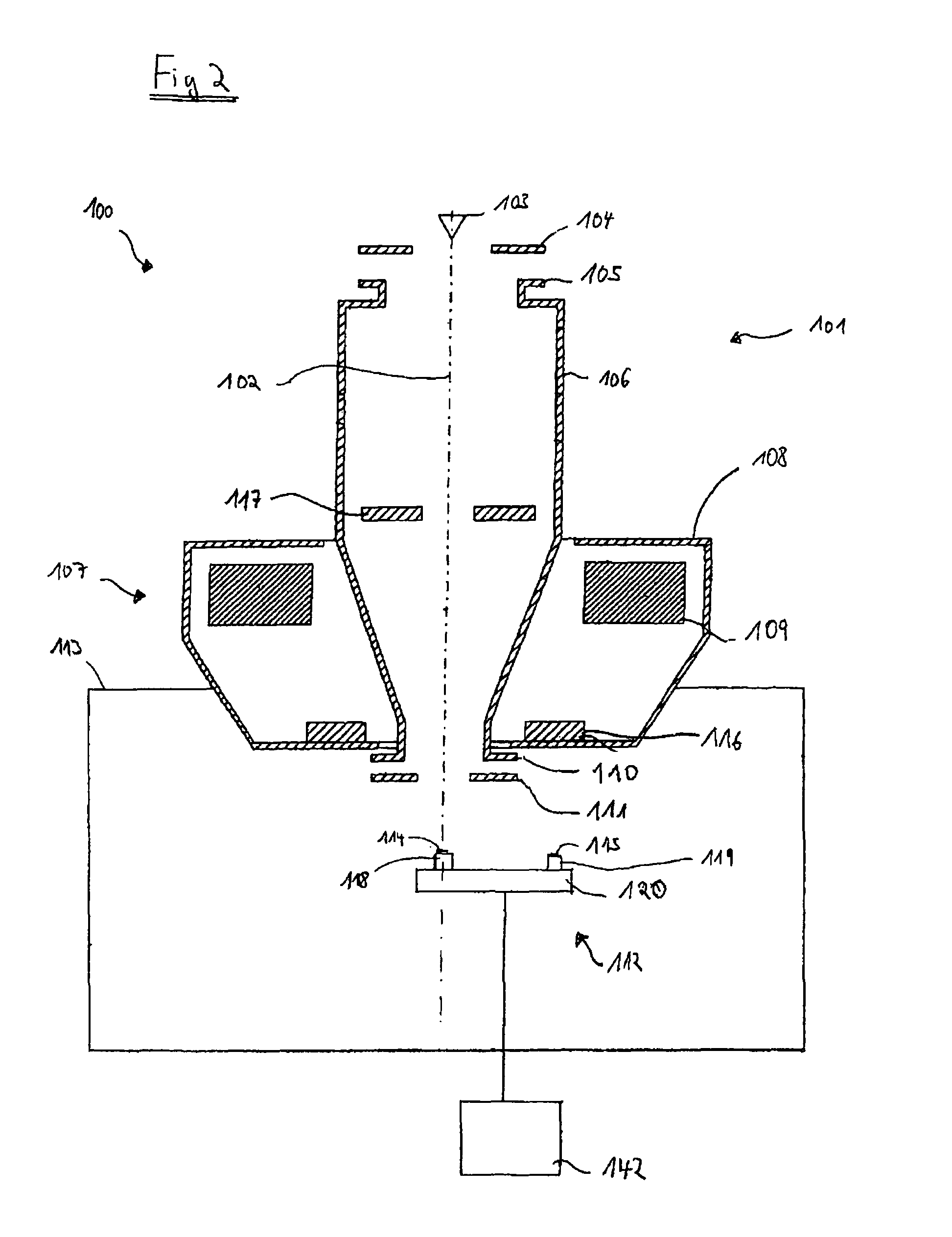
[0065]FIG. 2 shows a schematic illustration of a particle beam device 100 in the form of an SEM with a first particle beam column 101, which is embodied as an electron beam column. Reference is explicitly made already at this juncture to the fact that the system described herein is not restricted to an SEM. Rather, the system described herein can be used with any particle beam device, more particularly with an ion beam device.

[0066]The first particle beam column 101 has a first optical axis 102, a first beam generator in the form of an electron source 103 (cathode), a first electrode 104 in the form of an extraction electrode and a second electrode 105 in the form of an anode, which at the same time forms one end of a first beam guiding tube 106. By way of example, the electron source 103 is a thermal field emitter. Electrons that emerge from the electron source 103 are accelerated to an anode potential as a result of a potential difference between the electron source 103 and the se...


PUM


Abstract

A particle beam device and a sample receptacle apparatus, which has a sample holder, are disclosed. The sample holder is arranged in a movable fashion along at least a first axis and along at least a second axis. Furthermore, the sample holder is arranged in a rotatable fashion about a first axis of rotation and about a second axis of rotation. A first sample holding device is arranged relative to the sample holder in a rotatable fashion about a third axis of rotation, in which the third axis of rotation and the second axis of rotation are at least in part arranged laterally offset with respect to one another. Furthermore, a control apparatus is provided, in which the first sample holding device is rotatable about the third axis of rotation into an analysis position and / or treating position using the control apparatus.

Description

TECHNICAL FIELD[0001]This application relates to a particle beam device, more particularly an electron beam device or an ion beam device, which has a sample holder. This application also relates to a particle beam device with two particle beam columns, more particularly with an electron beam column and with an ion beam column, in which the particle beam device is provided with a sample holder.BACKGROUND OF THE INVENTION[0002]Electron beam devices, more particularly a scanning electron microscope (also referred to as an SEM herein), are used to analyze samples in order to obtain information in respect of the properties and behavior of these samples in specific conditions.[0003]In an SEM, an electron beam (also called primary electron beam herein) is generated using a beam generator and focused onto a sample to be analyzed using a beam guiding system, more particularly an objective lens. The primary electron beam is guided in a raster-like fashion over a surface of the sample to be an...

Claims


Application Information

Patent Timeline
Patent Type & Authority Patents(United States)
IPC IPC(8): H01J37/20H01J37/28
CPCH01J37/28H01J37/20H01J2237/201H01J2237/20207H01J2237/20214H01J2237/20221H01J2237/20285H01J2237/20292H01J2237/25H01J2237/202
Inventor BIBERGER, JOSEFPULWEY, RALPH
Owner CARL ZEISS MICROSCOPY GMBH
Why Eureka
Try Eureka