

Coaxial cable connector with radio frequency interference and grounding shield
a technology of radio frequency interference and coaxial cable, applied in the direction of electrical equipment, connection, coupling device connection, etc., can solve the problems of poor picture quality, poor data performance, and increase in customer complaints
- Summary
- Abstract
- Description
- Claims
- Application Information
AI Technical Summary
Benefits of technology
Problems solved by technology
Method used
Image

Examples
Embodiment Construction
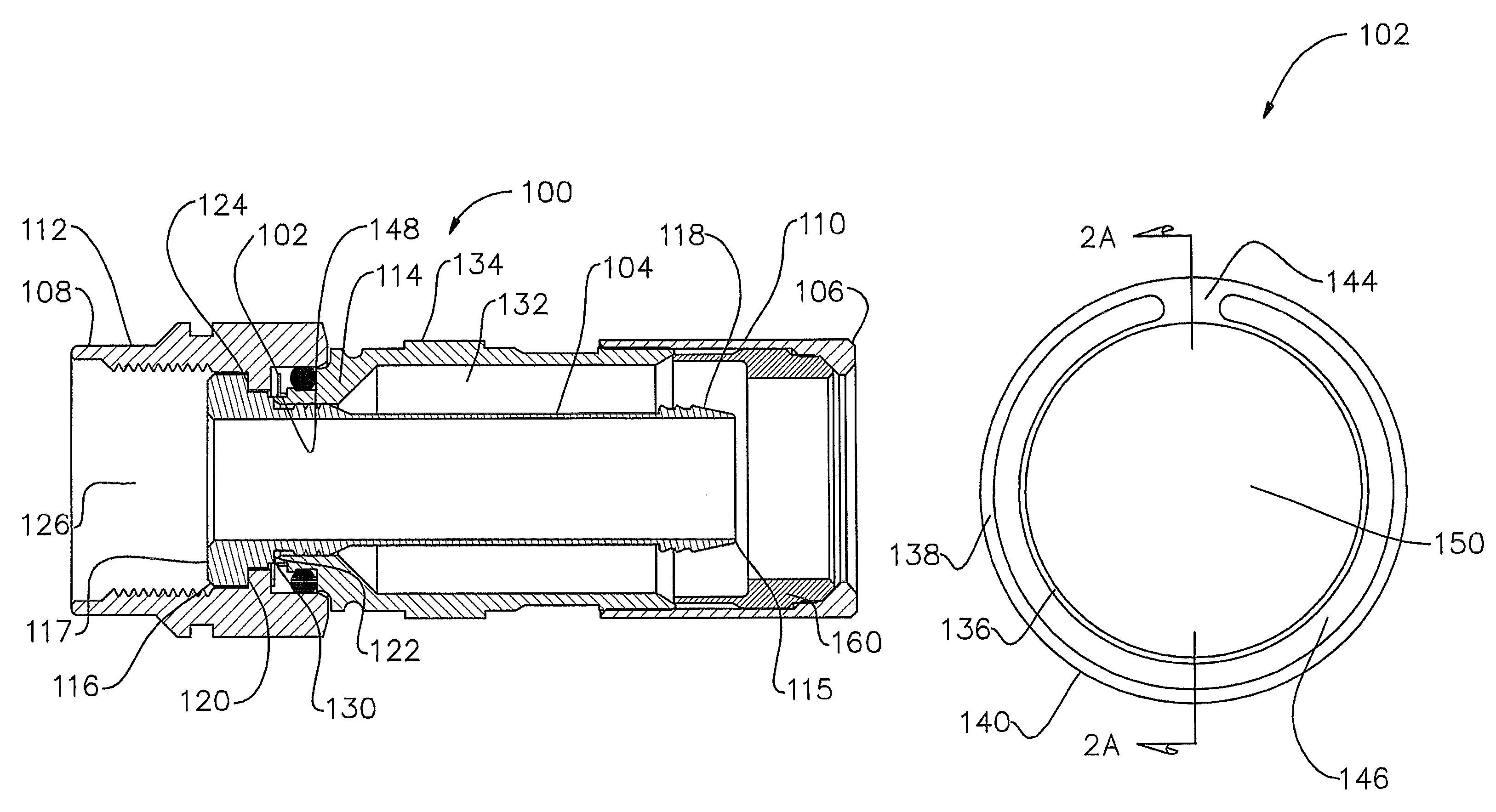
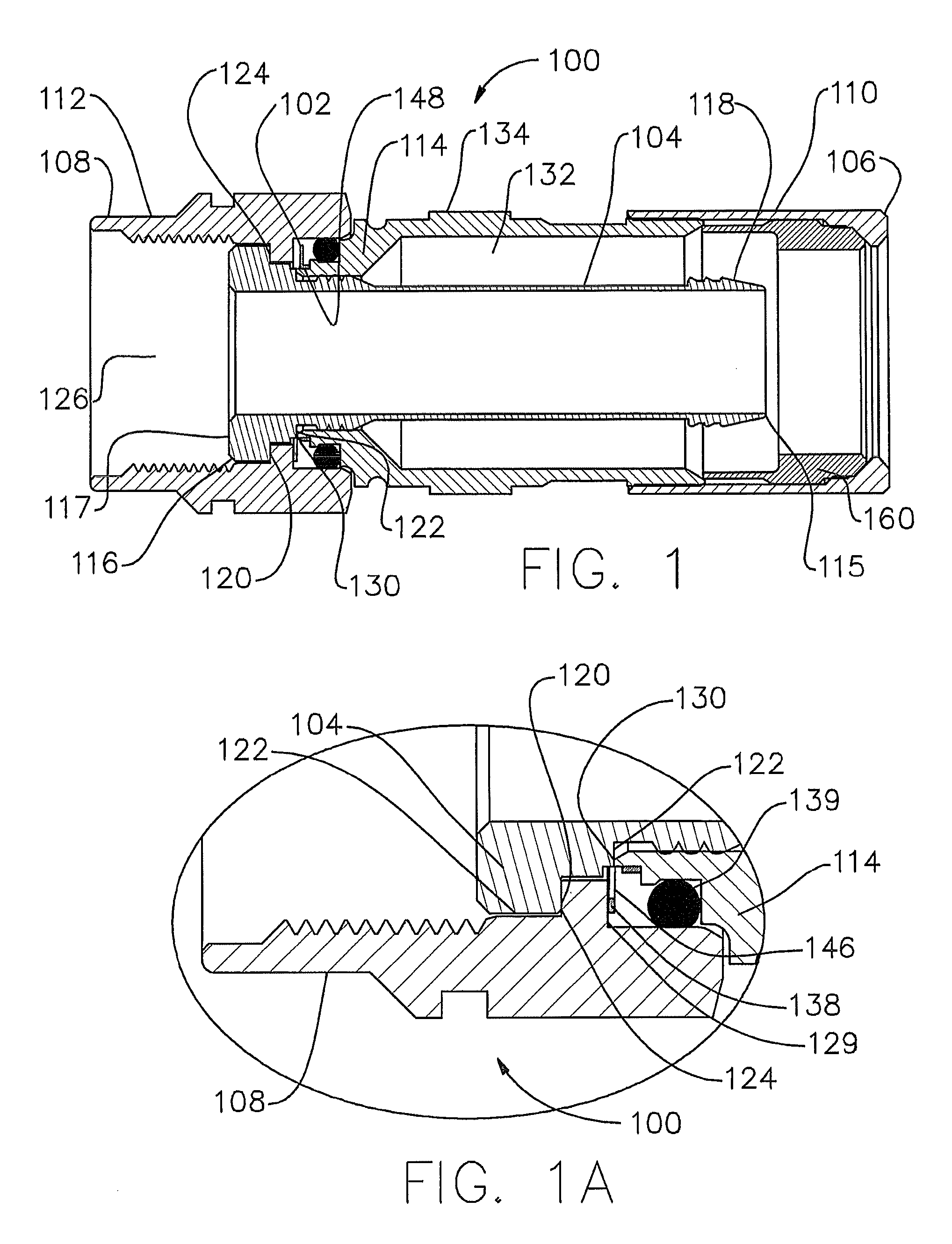
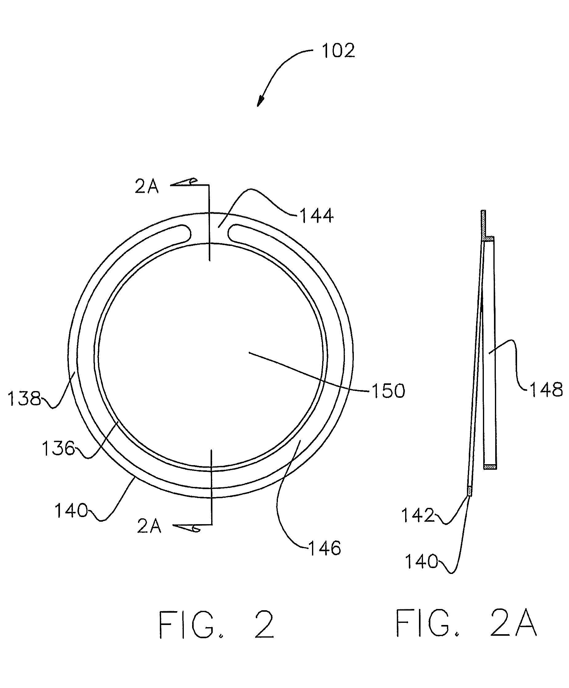
[0012]One embodiment includes a radio frequency interference (RFI) and grounding shield for a coaxial cable connector. The shield comprises an inner segment and at least one arcuately shaped pre-formed cantilevered annular beam attached to the inner segment by a joining segment. The at least one pre-formed cantilevered annular beam extends angularly from a plane of the circular inner segment. The at least one pre-formed cantilevered annular beam applies a spring-force to a surface of one of the coupler and body of the coaxial cable connector establishing an electrically conductive path between the components. The at least one pre-formed cantilevered annular beam comprises an outer surface with a knife-like edge that provides a wiping action of surface oxides on the coupler surface of the coaxial cable connector and allows for unrestricted movement when the coaxial cable connector is attached to an appliance equipment connection port of an appliance.
[0013]A further embodiment include...
PUM
 Abstract
Description
Claims
Application Information