
Method for improving the quality of data transmission in a packet-based communication network

data transmission technology, applied in the field of improving the quality of data transmission in a packet-based communication network, can solve the problems of network technology not being deployed in many application scenarios, no guarantees in delay and/or jitter, and technology only being deployed with the use of special hardwar

Active Publication Date: 2015-11-17
SIEMENS AG
View PDF9 Cites 0 Cited by
  • Summary
  • Abstract
  • Description
  • Claims
  • Application Information

AI Technical Summary

Benefits of technology

The patent describes a way to improve the quality of data transmission in a packet-based communication network by making it more deterministic and reducing delay and jitter. This is done by monitoring and addressing overload situations in real-time. The method allows for the setup of alternative communication paths to bypass overloaded ports and can also identify and improve critical situations caused by low-priority data traffic. Overall, the method helps to achieve high transmission quality, reducing reliance on complex calculations and modifications to network nodes.

Problems solved by technology

Because of complexity and high costs (e.g., in the case of scaling), the network technologies may not be deployed in many application scenarios.
However, one problem with packet-based communication networks is that no guarantees may be given as regards delay and / or jitter.
Although complex extensions of Ethernet (e.g., an isochronous real-time transmission (IRT) for PROFINET) that emulate a deterministic behavior of the communication network by TDM are known in the field of Industrial Ethernet, this technology may only be deployed with the use of special hardware and a highly complex configuration.

Method used


Image

  • Method for improving the quality of data transmission in a packet-based communication network
  • Method for improving the quality of data transmission in a packet-based communication network
  • Method for improving the quality of data transmission in a packet-based communication network

Examples


Embodiment Construction

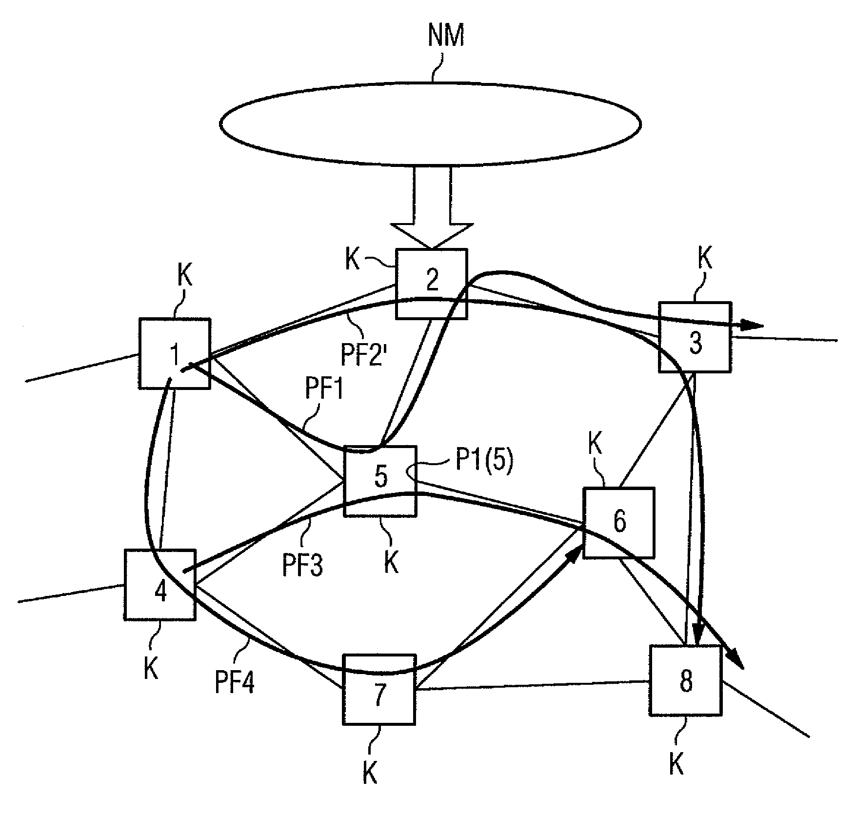
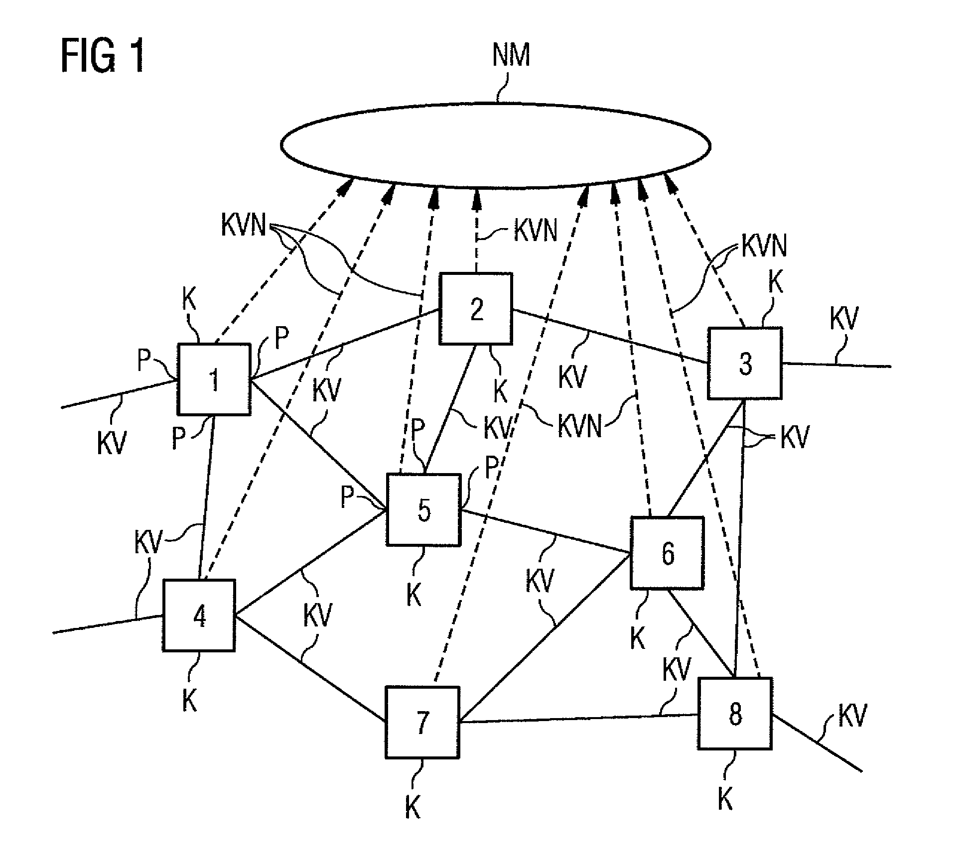
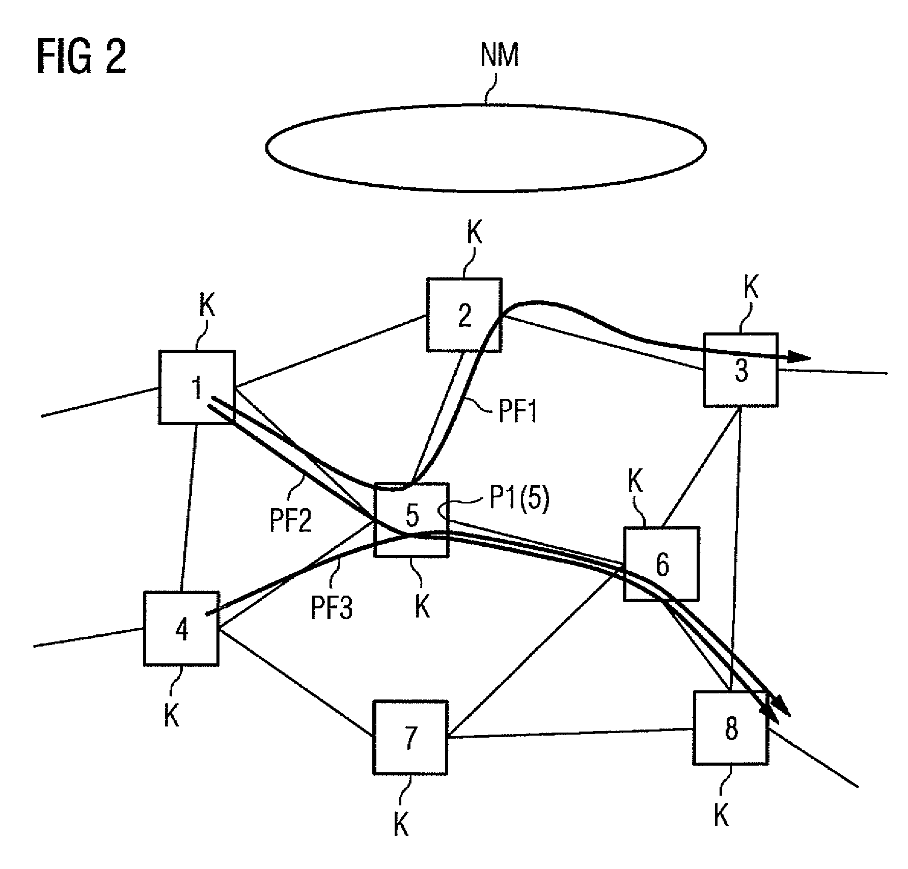
[0027]FIG. 1 shows a communication network including a plurality of network nodes K and a network management instance NM. The network nodes K are numbered from 1 to 8, where the figures represent a respective address of the network nodes K. Each of the network nodes K has a number of ports P, via which a communication connection KV to another network node K may be produced. In the present exemplary embodiment, the number of communication connections exiting from a node K corresponds to the number of ports. A respective node may have a larger number of ports than communication connections. Only for the nodes K characterized with the addresses 1 and 5 are the ports P provided with reference characters. The communication connections KV may, depending on the type of the communication network, be line-based or wireless in nature. For wireless communication connections KV, for example, communication connections other than those illustrated in FIG. 1 may be formed between the nodes K.

[0028...


PUM


Abstract

The embodiments relate to a method for improving the quality of data transmission in a packet-based communication network comprising a plurality of network nodes. Each network node has a number of ports with which at least one queue is associated respectively, and by which ports a communication connection to another network node may be produced. At least the queues of those ports that are arranged, in the network nodes, along respective communication paths that are formed in the communication network, are monitored for their queue length. A degree of overload of the affected port(s) is determined from the queue length, and a runtime delay and / or a delay variation in the data transmission may be inferred. The overload amount rises above a predetermined threshold value for at least one of the communication paths running across an overloaded port.

Description

[0001]The present patent document is a §371 nationalization of PCT Application Serial Number PCT / EP2012 / 050873, filed Jan. 20, 2012, designating the United States, which is hereby incorporated by reference. This patent document also claims the benefit of DE 10 2011 003 321.1, filed on Jan. 28, 2011, which is also hereby incorporated by reference.BACKGROUND[0002]The present embodiments relate to improving the quality in a packet-based communication network that includes a plurality of network nodes[0003]In many applications distributed across a communication network, the data transmission with respect to an end-to-end delay (e.g., delay) and / or a delay variation (e.g., jitter) is to not exceed specified limit values, so that the desired quality of service of the application is achieved. This applies, for example, to communication networks developed in the industrial sphere (e.g., for plant automation, process automation or energy automation). Only network technologies based on time d...

Claims


Application Information

Patent Timeline
IPC IPC(8): G01R31/08H04L12/26H04L12/24H04L12/803H04L12/863H04L12/835H04L12/851H04L12/707H04L12/703H04L12/801H04L45/121H04L45/24H04L45/28H04L47/30
CPCH04L47/50H04L41/0663H04L43/0852H04L45/22H04L45/28H04L47/11H04L47/122H04L47/18H04L47/24H04L47/29H04L47/30
Inventor RIEDL, JOHANNESSCHEFFEL, MATTHIAS
Owner SIEMENS AG
Learn More