Methods and system for controlled laser-driven explosive bonding

a laser-driven explosive and laser-driven technology, applied in the direction of transfer patterning, vacuum evaporation coating, conductive pattern formation, etc., can solve the problem of plastic deformation of the substrate at the location, achieve high pressure, increase the shear flow of material, and adhere to the underlying material high

Active Publication Date: 2015-11-17
LAWRENCE LIVERMORE NAT SECURITY LLC +1
View PDF2 Cites 16 Cited by
  • Summary
  • Abstract
  • Description
  • Claims
  • Application Information

AI Technical Summary

Benefits of technology

[0007]Embodiments of the present invention provide techniques for depositing one material over another that are applicable to a variety of types and alloy phase of materials, resulting in a coating that has high adhesion to the underlying material. Specifically, techniques provided herein use laser energy to accelerate a thin film of the material to be deposited to several hundred meters / sec resulting in the material hitting a substrate at an oblique angle and causing plastic deformation of the substrate at the location of impact. This generates very high pressure and increases the shear flow of material at the interface of the deposited material and the substrate, resulting in material intermixing with the substrate and thereby forming a strong bond between the deposited material and the underlying substrate.
[0010]Some embodiments of the present invention provide a system that comprises a laser source, a substrate holder, a coating material holder, and a fluid dispenser assembly. The system is configured to hold a substrate using the substrate holder, hold the coating material at a first distance from the substrate and at a first angle with respect to the substrate, flow a liquid over the coating material using the fluid dispenser assembly, impinge a laser beam at a first location on the coating material, generate a plasma characterized by a first pressure at an interface region of the liquid and the coating material, accelerate a portion of the coating material at the first location to a first velocity, and cause bonding of the portion of the coating material at the first location to the substrate.

Problems solved by technology

Specifically, techniques provided herein use laser energy to accelerate a thin film of the material to be deposited to several hundred meters / sec resulting in the material hitting a substrate at an oblique angle and causing plastic deformation of the substrate at the location of impact.

Method used


Image

  • Methods and system for controlled laser-driven explosive bonding
  • Methods and system for controlled laser-driven explosive bonding
  • Methods and system for controlled laser-driven explosive bonding

Examples


Embodiment Construction

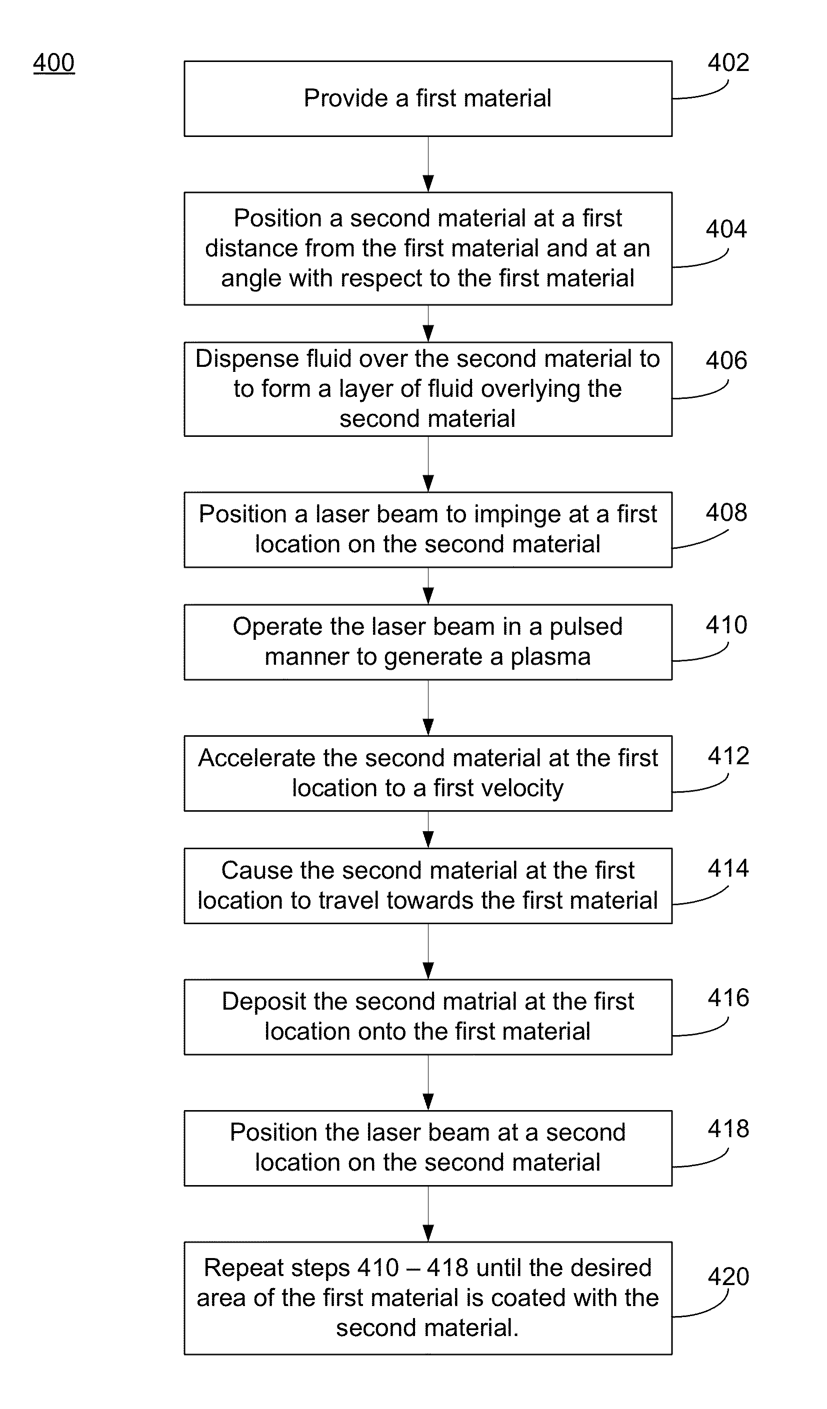
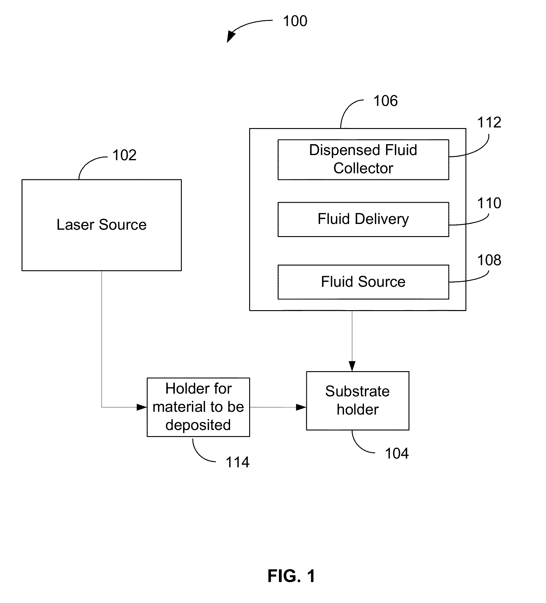
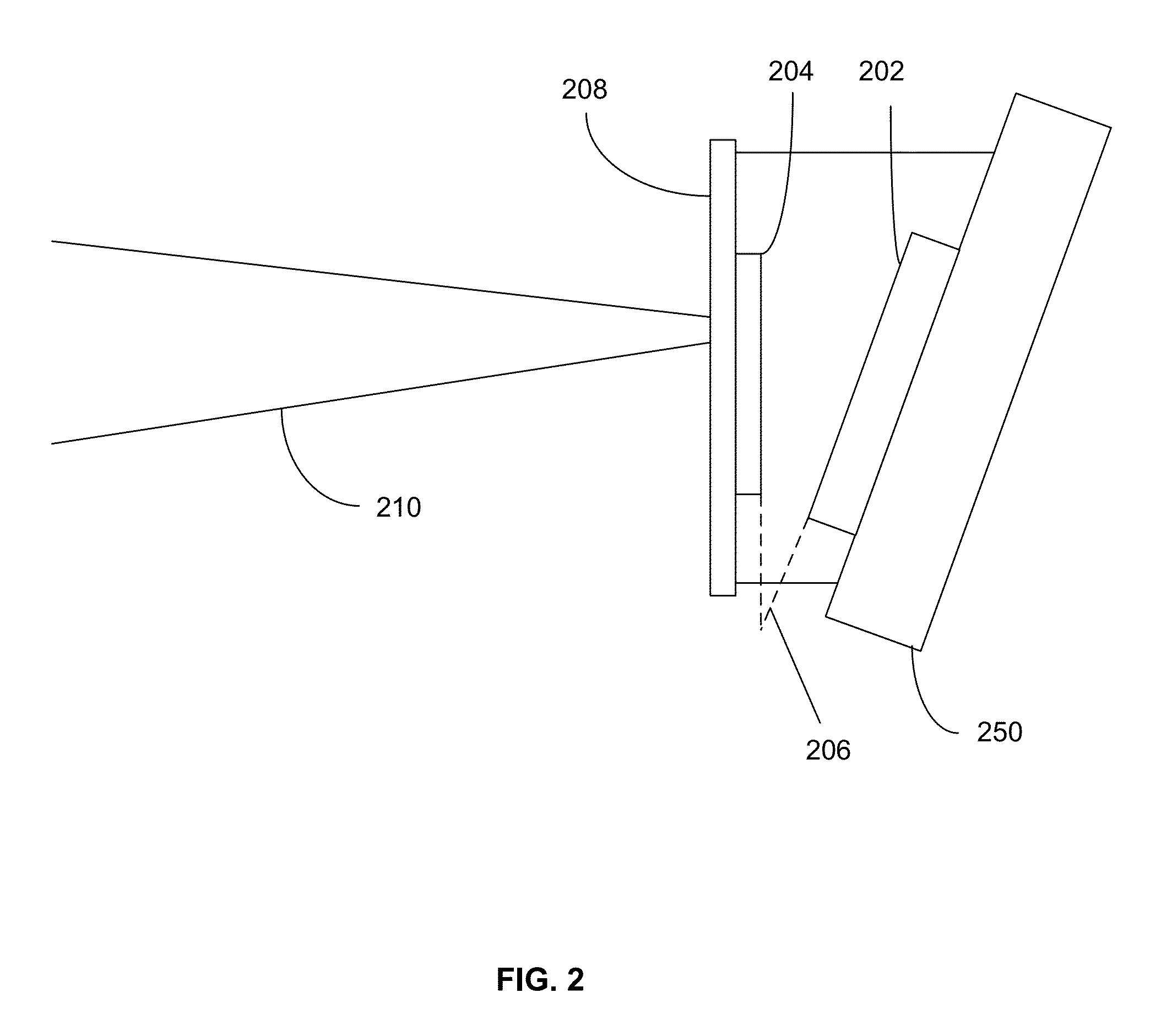
[0017]The present disclosure is related to bonding or coating of materials in general. Specifically, techniques disclosed herein provide methods and systems for coating a first material with a second material using a laser.

[0018]Coatings produced with chemical and / or physical vapor deposition processes are produced at a slow rate due to mass flux limitations. Low mass flux and roughness amplification can place practical limitations on coating thickness. In addition, these processes can only be used for producing coatings with a relatively narrow range of elemental compositions. Typically, conventional thermal and cold spray coatings have bond strengths on the order of 10,000 pounds per square inch (psi), while the substrate and coating material can have ultimate tensile strengths on the order of 100,000 to 500,000 psi. Furthermore, conventional coating processes such as the thermal spray process, rely on powder feeds through a hypersonic nozzle, which is difficult to manage and oper...


PUM

PropertyMeasurementUnit
distanceaaaaaaaaaa
velocityaaaaaaaaaa
velocityaaaaaaaaaa

Abstract

A technique for bonding two dissimilar materials includes positioning a second material over a first material at an oblique angle and applying a tamping layer over the second martial. A laser beam is directed at the second material that generates a plasma at the location of impact on the second material. The plasma generates pressure that accelerates a portion of the second material to a very high velocity and towards the first material. The second material impacts the first material causing bonding of the two materials.

Description

STATEMENT AS TO RIGHTS TO INVENTIONS MADE UNDER FEDERALLY SPONSORED RESEARCH OR DEVELOPMENT[0001]The United States Government has rights in this invention pursuant to Contract No. DE-AC52-07NA27344 between the U.S. Department of Energy and Lawrence Livermore National Security, LLC, for the operation of Lawrence Livermore National Laboratory.BACKGROUND[0002]Coatings are an essential component of modern, high performance systems and equipment. They can provide corrosion and corrosion cracking protection, extended wear, insulation, and voltage-standoff. However conventional techniques for coatings often result in less than desirable performance characteristics such as less than desired adhesion and low density. In other cases, desirable coatings cannot be applied because the available coating processes cannot achieve the desired phase, stoichiometry, or alloy structure.[0003]Several techniques are currently available for deposition of one material over another or bonding of one materia...

Claims


Application Information

Patent Timeline
Patent Type & Authority Patents(United States)
IPC IPC(8): C23C14/30H05B7/00H05K3/14C23C14/14C23C14/28H05K3/10
CPCH05K3/14C23C14/14C23C14/28H05K3/10H05K2203/0528H05K2203/107H05K2203/1527
Inventor RUBENCHIK, ALEXANDER M.FARMER, JOSEPH C.HACKEL, LLOYDRANKIN, JON
Owner LAWRENCE LIVERMORE NAT SECURITY LLC
Why Eureka
Try Eureka