Anchor member for vertebral osteosynthesis equipment

a technology of vertebral osteosynthesis and anchor member, which is applied in the field of anchor member for vertebral osteosynthesis equipment, can solve the problems of most often bothersome inclined positions

Active Publication Date: 2015-11-24
MEDICREA INT SA
View PDF62 Cites 20 Cited by
  • Summary
  • Abstract
  • Description
  • Claims
  • Application Information

AI Technical Summary

Benefits of technology

[0008]The anchor member to which it relates comprises, in a known manner, an anchoring base including a peripheral proximal wall that inwardly delimits a proximal cavity, and a proximal stud including a distal articulation portion received in said proximal cavity, said proximal wall including a peripheral proximal rim oriented toward the axis of said proximal cavity, ensuring retention of said distal articulation portion in that proximal cavity; said proximal cavity has an axis, said proximal wall has an inner surface on the side of said proximal cavity, and said proximal stud has a longitudinal axis.
[0011]the anchor member comprises an elastically deformable element placed in the bottom of said proximal cavity, having a curved shape and an apex, said apex of said elastically deformable element being situated substantially at the axis of said proximal cavity, said convex distal surface bearing against said elastically deformable element, and the latter being permanently elastically deformed such that it continuously presses said distal articulation portion against said peripheral proximal rim in order to generate friction between said distal articulation portion and said peripheral proximal rim capable of keeping the proximal stud in a predetermined position without preventing the stud from moving into another position.
[0012]Owing to this friction and to the friction exerted between said convex distal surface and said elastically deformable element, the proximal stud keeps its predetermined position, notwithstanding the gravitational force it undergoes, and can be placed in another position, which it will also keep. The convex shape of said distal surface and the curved shape of the elastically deformable element make it possible (i) to obtain a contact surface between the respective apices of said surface and the elastically deformable element remaining substantially situated at the axis of the base, and (ii) to obtain a recess between the periphery of said surface and the periphery of said elastically deformable element, meaning that the periphery of said convex distal surface does not bear against the periphery of the elastically deformable element when the proximal stud is inclined. These conditions are necessary to preserve the incline of the stud.
[0024]Preferably, the aforementioned peripheral proximal rim of said proximal wall delimiting said proximal cavity has a series of notches capable of partially receiving the proximal stud and thereby allowing increased travel of said proximal stud relative to the anchoring base.
[0025]This increased travel is not only favorable in terms of use of the anchor member, but also makes it possible to ensure proper maintenance of the stud in the maximum angulation position.

Problems solved by technology

These inclined positions are most often bothersome in the implantation site, which is deep and has small dimensions.

Method used


Image

  • Anchor member for vertebral osteosynthesis equipment
  • Anchor member for vertebral osteosynthesis equipment
  • Anchor member for vertebral osteosynthesis equipment

Examples


Embodiment Construction

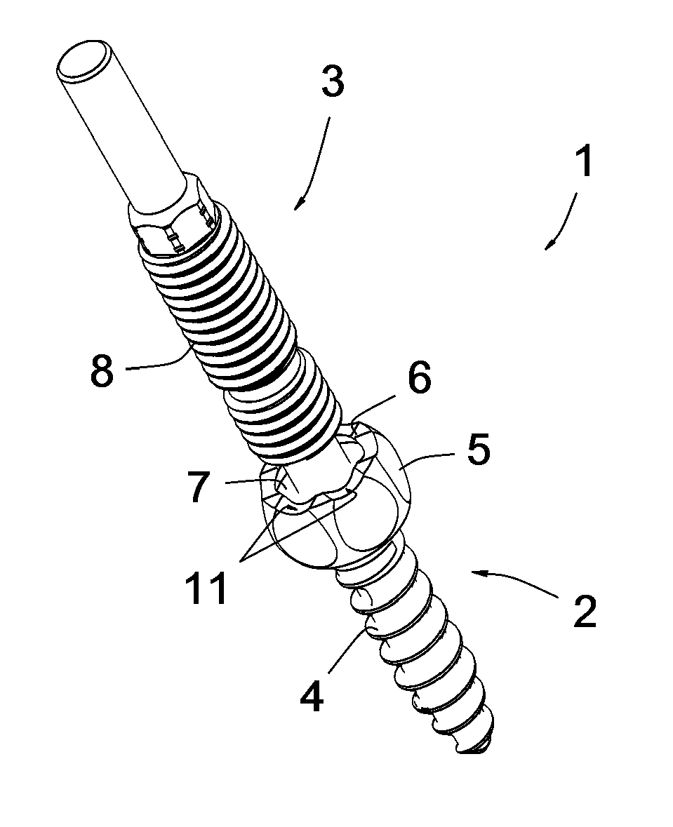
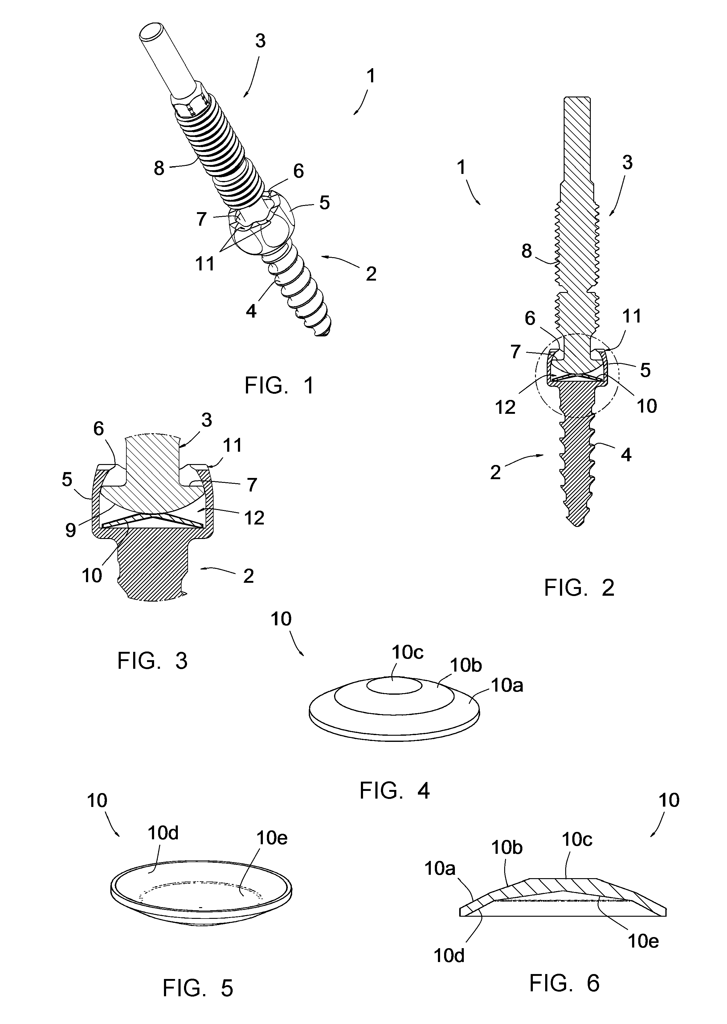
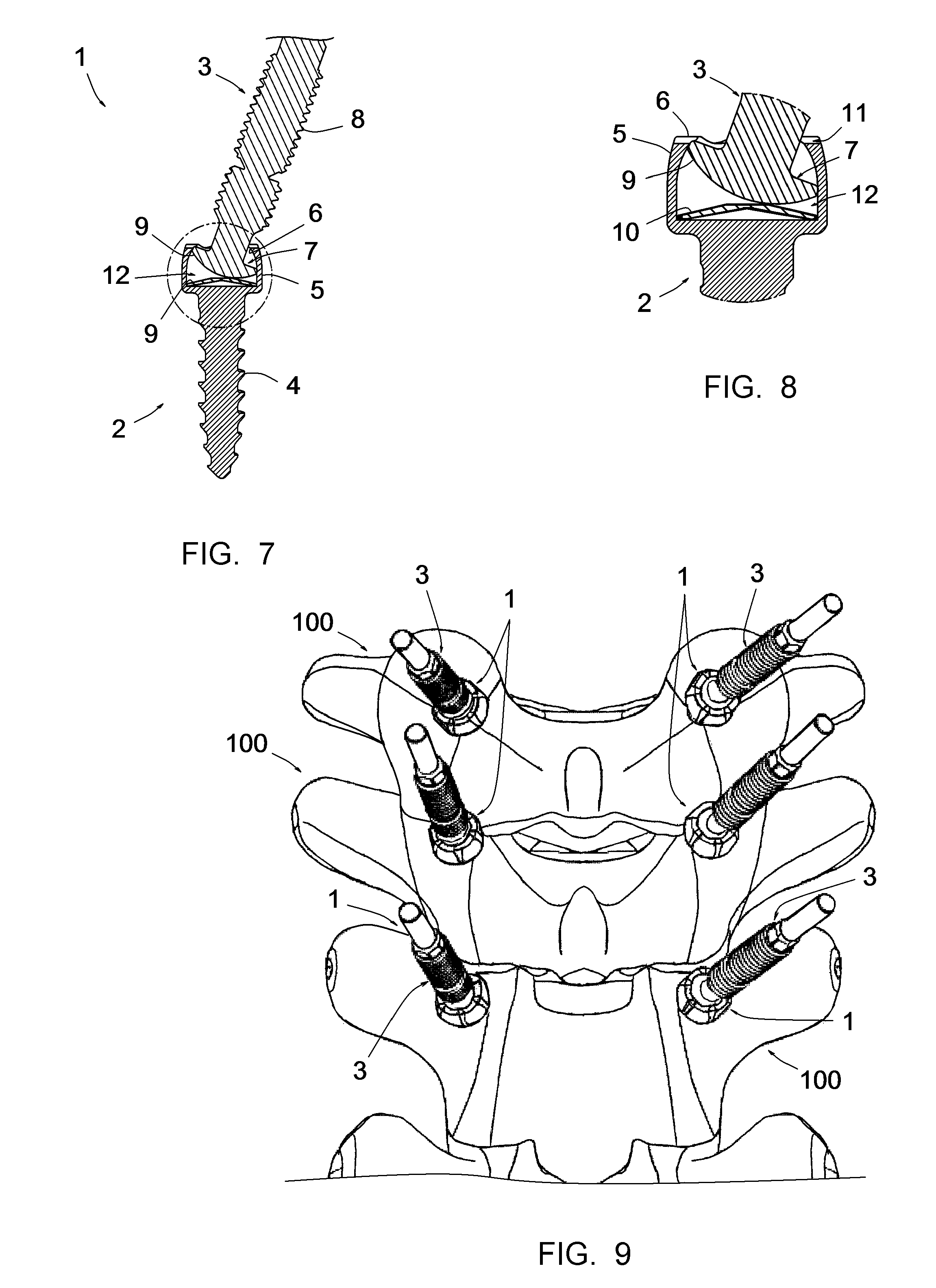
[0037]The anchor member 1 is of the “polyaxial” type, i.e. it comprises a bone anchoring base 2 and a threaded proximal stud 3, the stud 3 being articulated relative to said base 2. In the illustrated example, the base 2 comprises a threaded body 4 intended to be screwed in the pedicle of a vertebra 100 (cf. FIG. 9); the space 2 could also in particular comprise a laminar hook or a flexible link intended to form a loop around a vertebral lamina or a vertebral apophysis.

[0038]The base 2 comprises a head including a proximal wall 5 that inwardly delimits a proximal articulation cavity of the stud 3. This wall has a faceted outer surface, allowing the base 2 to be grasped by a screwing instrument in order to screw said base 2 into the pedicle of a vertebra. It includes a thickened peripheral proximal rim 6 curved toward the axis of the base 2, which ensures retention in said proximal cavity of the distal articulation portion 7. This rim 6 and the wall 5 have a series of eight notches 1...


PUM


Abstract

The anchor member (1) includes an anchoring base (2) having a peripheral proximal wall (5) that inwardly delimits a proximal cavity, and a proximal stud (3) including a distal articulation portion (7) received in the proximal cavity, the proximal wall (5) including a peripheral proximal rim (6) ensuring retention of the distal articulation portion (7) in that proximal cavity. According to the invention, the distal articulation portion (7) has a peripheral edge dimensioned to come into the immediate vicinity of the inner surface of the proximal wall (5), and has a convex distal surface (9) whereof the apex is situated substantially at the axis of the proximal stud (3); and the anchor member (1) includes an elastically deformable element (10) placed in the bottom of said proximal cavity, having a curved shape whereof the apex is situated substantially at the axis of the proximal cavity, the surface (9) bearing against this element (10), and the latter being permanently elastically deformed such that it continuously presses the portion (7) against the rim (6).

Description

CROSS REFERENCE TO RELATED APPLICATION[0001]This application is a national stage entry of PCT / IB2012 / 053717 filed Jul. 20, 2012, under the International Convention claiming priority over French Application No. 1156727 filed Jul. 25, 2011.FIELD OF THE INVENTION[0002]The present invention relates to an anchor member for vertebral osteosynthesis equipment.BACKGROUND OF THE INVENTION[0003]To immobilize part of the vertebral column, in particular to treat the degeneration of an intervertebral disc, it is well known to use vertebral osteosynthesis equipment comprising anchor members for anchoring to the vertebrae (pedicular screws and / or laminar hooks), connecting rods making it possible to connect said anchor members to one another, and connectors making it possible to connect said connecting rods to said anchor members.[0004]An anchor member is frequently “polyaxial,” i.e. comprises a threaded proximal stud articulated relative to an anchoring base, the stud comprising a distal articula...

Claims


Application Information

Patent Timeline
Patent Type & Authority Patents(United States)
IPC IPC(8): A61B17/86A61B17/70A61B19/00
CPCA61B17/70A61B17/7035A61B17/7041A61B17/8695A61B2019/307A61B2090/037
Inventor MEYRAT, RICHARDFUENTES, STEPHANE
Owner MEDICREA INT SA
Why Eureka
Try Eureka