Head unit, ultrasonic probe, electronic instrument, and diagnostic device

a technology of ultrasonic probe and head unit, which is applied in the field of head unit, ultrasonic probe, electronic instrument, and diagnostic device, can solve the problems of expensive repair cost or the like, and the need to replace the entire probe, and achieve the effect of efficient ultrasonic diagnosis

Inactive Publication Date: 2015-11-24
SEIKO EPSON CORP
View PDF19 Cites 3 Cited by
  • Summary
  • Abstract
  • Description
  • Claims
  • Application Information

AI Technical Summary

Benefits of technology

[0009]With this aspect, since the probe main body and the head unit can be electrically connected through the connecting section and the head unit can be removably coupled with the probe main body, the head unit can be replaced in a case where the element chip is damaged. As a result, the repair cost can be reduced and user-friendliness can be improved in an ultrasonic diagnostic device, for example.
[0015]With this configuration, the first group of chip terminals and the second group of chip terminals are disposed in the peripheral portion of the element chip along the first side and the second side. In such a case, the first group of chip terminals and the first connector can be connected through the first flexible printed circuit board, and the second group of chip terminals and the second connector can be connected through the second flexible printed circuit board. Further, driving signals are input to the first group of chip terminals and the second group of chip terminals, thereby reducing decrease in the driving signal voltage due to the wiring resistance. Consequently, higher radiation intensity of ultrasonic waves can be obtained.
[0017]With this configuration, when the first group of chip terminals and the second group of chip terminals are disposed in the peripheral portion of the element chip along the first side and the second side, the element chip and the probe main body can be electrically connected through the first group of connecting terminals and the second group of connecting terminals. Further, driving signals are input to the first group of chip terminals and the second group of chip terminals, thereby reducing decrease in the driving signal voltage due to the wiring resistance. Consequently, higher radiation intensity of ultrasonic waves can be obtained.
[0019]With this configuration, since the element chip can be inspected, it is possible to check whether the element chip is abnormal or not, for example, when the head unit is replaced. As a result, a highly reliable ultrasonic probe in which the head unit is replaceable can be achieved.
[0030]With this configuration, in an ultrasonic diagnostic device, for example, the head unit can be replaced depending on a target to be diagnosed, and control processing suitable for the target to be diagnosed can be conducted. As a result, efficient ultrasonic diagnosis becomes possible.

Problems solved by technology

The technique disclosed in the above mentioned publication, however, has a problem that the entire probe needs to be replaced or repaired when the piezoelectric element is deteriorated over time or damaged, and the repair cost or the like is expensive.

Method used


Image

  • Head unit, ultrasonic probe, electronic instrument, and diagnostic device
  • Head unit, ultrasonic probe, electronic instrument, and diagnostic device
  • Head unit, ultrasonic probe, electronic instrument, and diagnostic device

Examples


Embodiment Construction

[0046]Next, preferred embodiments of the present invention will be explained in detail. The embodiments explained below shall not be construed as unreasonably limiting the subject matter of the present invention described in the claims, and all the elements explained in the embodiments are not necessarily essential to the solving means of the present invention.

1. Ultrasonic Transducer Element

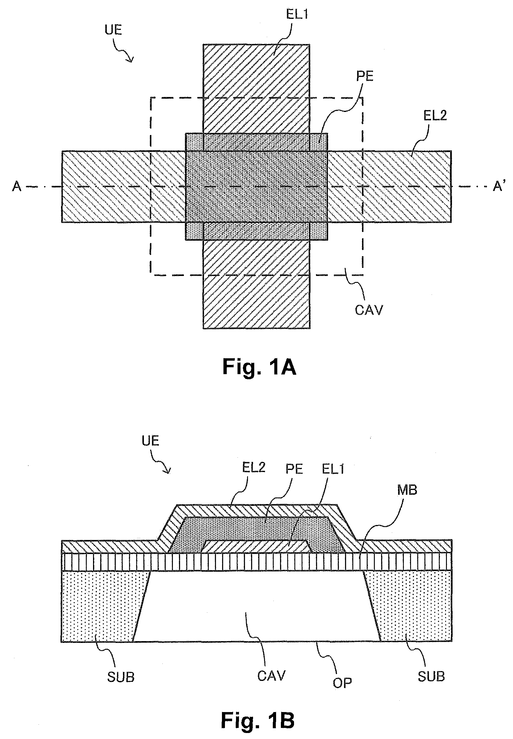
[0047]FIG. 1A and FIG. 1B show an example of a basic configuration of an ultrasonic transducer element (one example of an ultrasonic element) UE that is included in a head unit according to the present embodiment. The ultrasonic transducer element UE according to the present embodiment includes a first electrode layer EL1, a piezoelectric body layer PE, a second electrode layer EL2, a membrane (one example of a supporting member) MB, and a cavity region (cavity section) CAV. The ultrasonic transducer element UE according to the present embodiment is not limited to the configuration of FIG. 1, an...


PUM


Abstract

A head unit for an ultrasonic probe includes a connecting section, an element chip and a supporting member. The connecting section is configured to electrically connect the head unit to a probe main body of the ultrasonic probe. The element chip is configured to be electrically connected to the probe main body through the connecting section. The element chip includes a substrate and an ultrasonic element array. The substrate defines a plurality of openings arranged in an array pattern. The ultrasonic element array includes a plurality of ultrasonic transducer elements, with each of the ultrasonic transducer elements being provided in each of the openings of the substrate. The supporting member supports the element chip.

Description

CROSS-REFERENCE TO RELATED APPLICATIONS[0001]This application claims priority to Japanese Patent Application No. 2012-038361 filed on Feb. 24, 2012. The entire disclosure of Japanese Patent Application No. 2012-038361 is hereby incorporated herein by reference.BACKGROUND[0002]1. Technical Field[0003]The present invention relates to a head unit, an ultrasonic probe, an electronic instrument, and a diagnostic device.[0004]2. Related Art[0005]An ultrasonic diagnostic device for testing the inside of a human body, for example, has been known as a device in which ultrasonic waves are emitted toward a target and reflected waves are received from the boundary between different acoustic impedances inside the target. In Japanese Laid-Open Patent Publication No. 2007-142555, a technique in which ultrasonic beams are emitted by arranging piezoelectric elements in a matrix array pattern has been disclosed as an ultrasonic probe used for an ultrasonic diagnostic device.SUMMARY[0006]The technique...

Claims


Application Information

Patent Timeline
Patent Type & Authority Patents(United States)
IPC IPC(8): B06B1/06A61B8/00
CPCB06B1/0622A61B8/4494
Inventor TAKAHASHI, MASAKI
Owner SEIKO EPSON CORP
Why Eureka
Try Eureka