Self-ballasted, roof-integrated, lightweight FRC PV mounting system

a photovoltaic module and lightweight technology, applied in the direction of heat collector mounting/support, machine supports, light and heating equipment, etc., can solve the problems of damage to the roof, time-consuming process, and high cost of adjustable mounted arrays, so as to achieve easy and inexpensive manufacturing, and installation with little time and labor

Active Publication Date: 2015-11-24
SAUDI ARABIAN OIL CO
View PDF22 Cites 5 Cited by
  • Summary
  • Abstract
  • Description
  • Claims
  • Application Information

AI Technical Summary

Benefits of technology

[0009]Applicant has recognized a need for a system and method for mounting PV modules that can be installed without physically or mechanically attaching the module-mounting structure to the building roof and which can be installed with little time and labor. A need also exists for a mounting system that can be manufactured easily and inexpensively. These needs are met by the present technology as described and claimed below.
[0012]In yet other embodiments of the current technology, the upper mounting members and lower mounting members can position the photovoltaic module substantially horizontal. Alternatively, the upper mounting members and lower mounting members can position the photovoltaic module at a low incidence angle relative to a horizontal plane to ease the cleaning the of PV module. The strut member can include at least one opening for the passage of a cable.
[0017]In still other embodiments the step of securing the upper edge of the photovoltaic module to the upper mounting members with the connector means includes positioning the photovoltaic module at a low incidence angle relative to a horizontal plane to ease the cleaning the of PV module. The building roof can be a flat roof and can be located in a lower latitude region and the step of providing a plurality of ballast tiles can further include positioning the ballast tiles on the roof. The ballast tiles can be positioned directly adjacent to each other on the building roof.
[0020]In certain embodiments, the fiber reinforced concrete can be selected from a group consisting of alkaline-resistant glass and polymer fiber. In addition, the second mounting member can be secured to the upper edge of the photovoltaic module using a connector selected from a group consisting of a bolt, and a threaded clamp with an adjustable opening. The first and second mounting members can operable to position the photovoltaic module substantially horizontal. Alternately, the first and second mounting members are operable to position the photovoltaic module at a low incidence angle relative to a horizontal plane to ease the cleaning the of PV module. In embodiments where the at least one ballast tile is a plurality of ballast tiles, spacer tiles can be positioned between the plurality of ballast tiles.

Problems solved by technology

However, the adjustable mounted array is generally more expensive than fixed units (i.e units that are physically interconnecting) that are suitable in lower altitude countries.
While this technique can provide a more rigid attachment of the PV module, it is a time-consuming process and permanently damages the rooftop.
Also, because holes are formed into the rooftop, water damage can arise.
However, because PV modules are large flat structures, gusts of wind acting under a PV module can create lifting forces large enough to displace the PV module.
PV modules can be weighted to increase wind resistance, however, roofs have weight load limitations.

Method used


Image

  • Self-ballasted, roof-integrated, lightweight FRC PV mounting system
  • Self-ballasted, roof-integrated, lightweight FRC PV mounting system
  • Self-ballasted, roof-integrated, lightweight FRC PV mounting system

Examples


Embodiment Construction

[0041]The foregoing aspects, features, and advantages of the present technology will be further appreciated when considered with reference to the following description of preferred embodiments and accompanying drawings, wherein like reference numerals represent like elements. In describing the preferred embodiments of the technology illustrated in the appended drawings, specific terminology will be used for the sake of clarity. However, the technology is not intended to be limited to the specific terms used, and it is to be understood that each specific term includes equivalents that operate in a similar manner to accomplish a similar purpose.

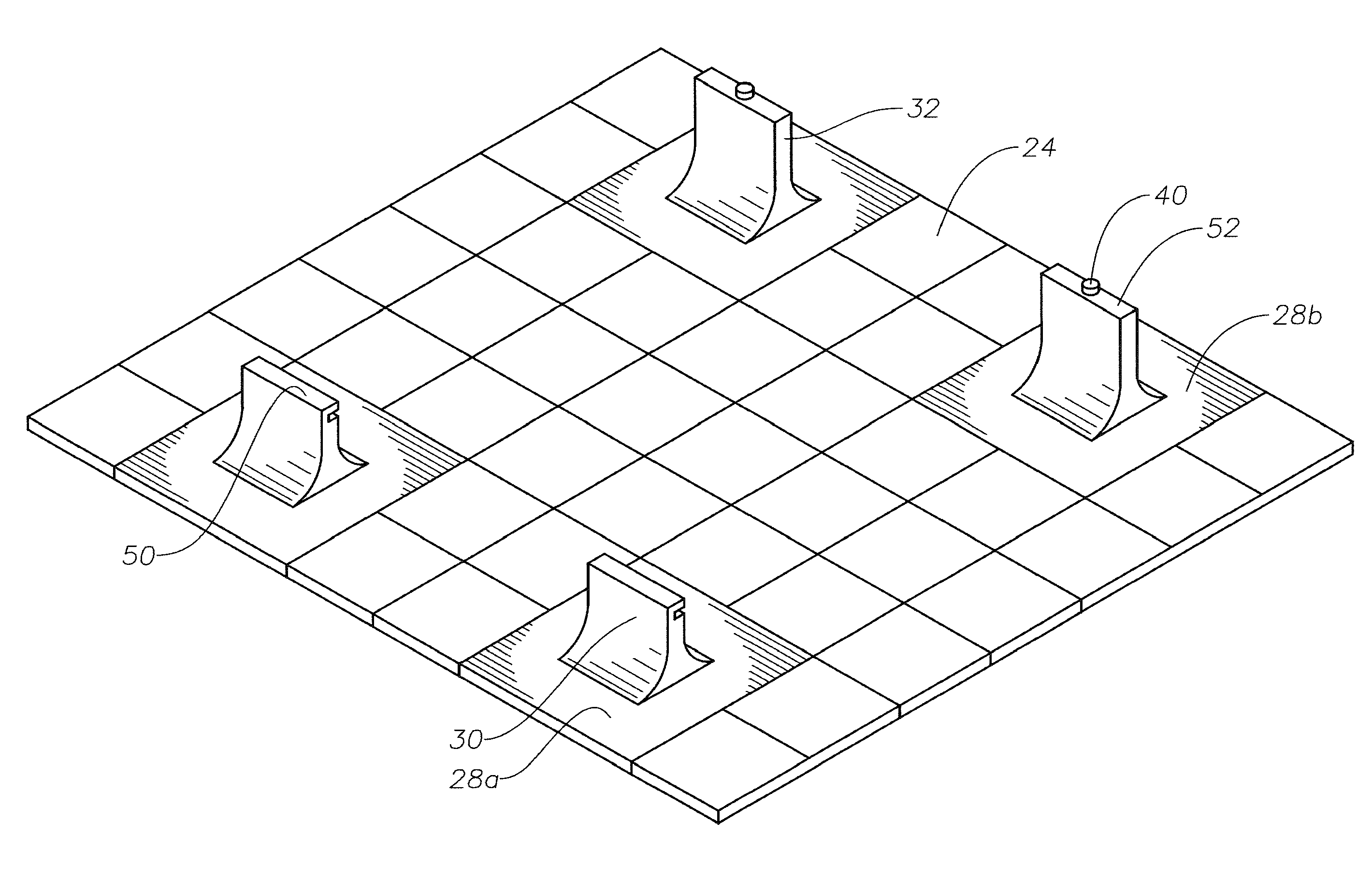
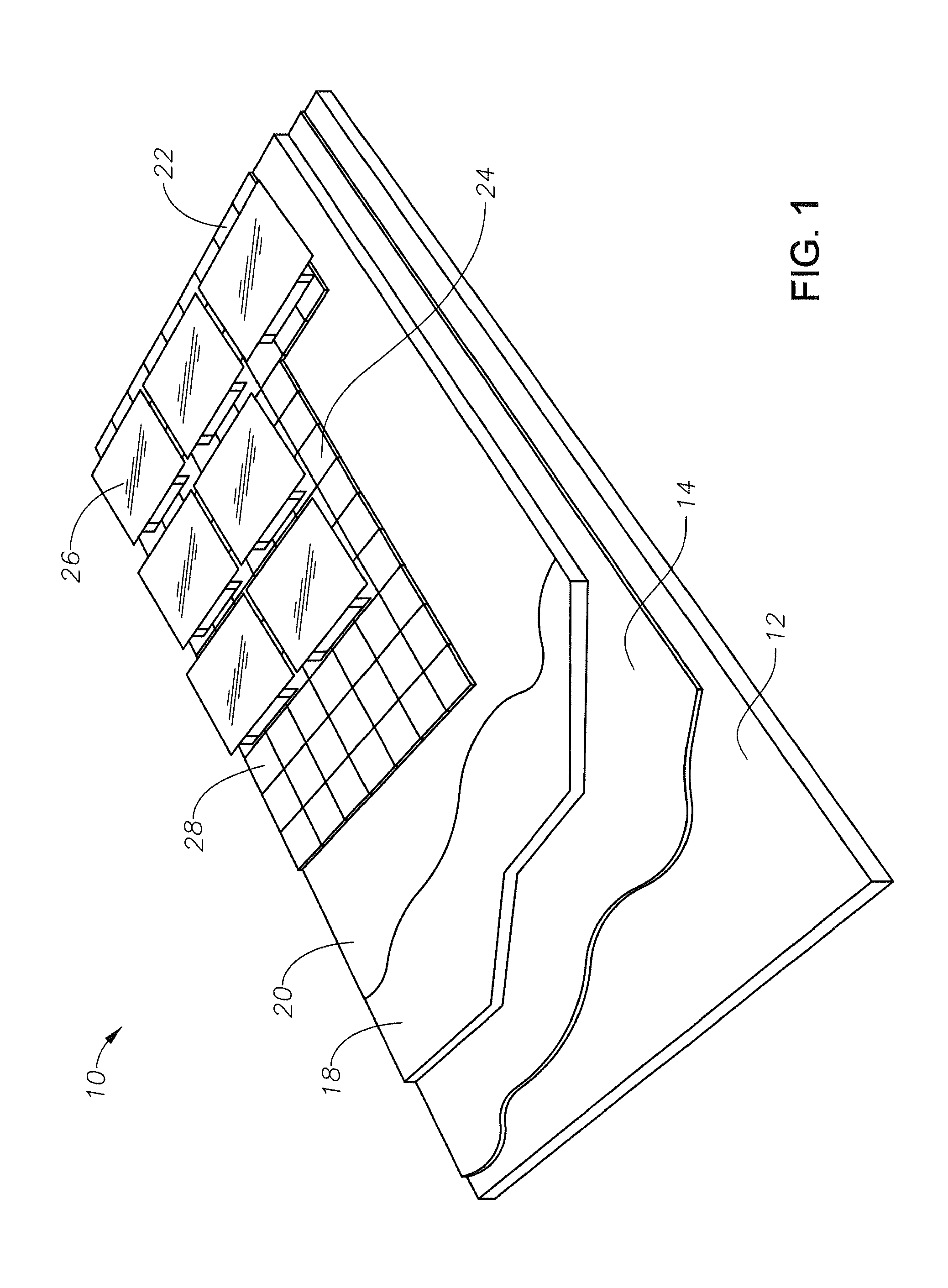
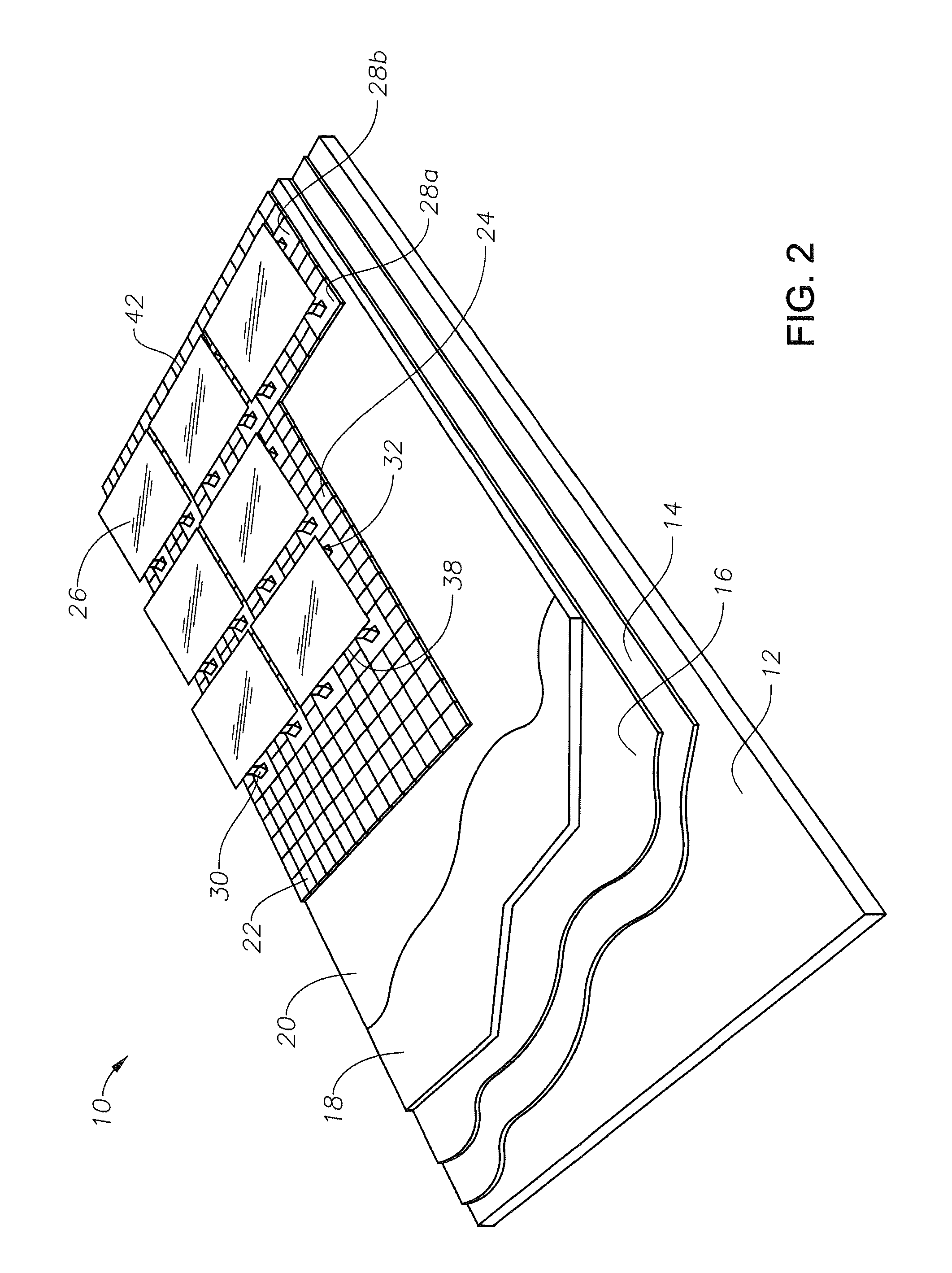
[0042]As can be seen in the embodiments shown in FIGS. 1 and 2, a typical insulated inverted roofing system, or protected membrane roof 10, can include multiple layers installed over a roof slab 12. Insulated inverted roofing systems or protected membrane roofs have become the standard in the design of modern flat roofs typically used in the co...


PUM


Abstract

A ballast tile system for supporting photovoltaic modules that includes at least one fiber-reinforced concrete ballast tile. The at least one ballast tile has a first mounting member extending upwardly from a top surface thereof, the first mounting member configured to receive a lower end of a photovoltaic module. The at least one ballast tile also has a second mounting member extending upwardly from the top surface thereof, the second mounting member configured to secure an upper edge of the photovoltaic module.

Description

CROSS REFERENCE TO RELATED APPLICATIONS[0001]This application claims priority to and the benefit of U.S. Provisional Application Ser. Nos. 61 / 655,814 and 61 / 655,875, both of which were filed Jun. 5, 2012, the full disclosures of which are hereby incorporated herein by reference.BACKGROUND OF THE INVENTION[0002]1. Field of the Invention[0003]The present technology relates to mountings for photovoltaic modules. More specifically, the technology relates to a self-ballasted, roof-integrated, lightweight fiber reinforced concrete system and method for mounting photovoltaic modules.[0004]2. Description of the Related Art[0005]Solar power is as an important alternative energy source. Solar photovoltaic (PV) technology is an approach for large scale solar energy collection. PV technology has demonstrated to be an economically and technologically feasible approach to supplying sustainable energy in buildings. Solar photovoltaic systems utilize solar modules to convert sunlight into electrici...

Claims


Application Information

Patent Timeline
Patent Type & Authority Patents(United States)
IPC IPC(8): E04D13/18F16M11/00F24J2/52H02S20/24
CPCF24J2/523F24J2/525H02S20/24F24J2/5245F16M11/00Y02B10/12Y02B10/20Y02E10/50F24S25/10F24S25/61F24S25/617Y02B10/10Y02E10/47
Inventor KHOWAITER, AHMAD O.
Owner SAUDI ARABIAN OIL CO
Why Eureka
Try Eureka