
Cooler transporting device

a cooler and transporting device technology, applied in transportation and packaging, skating, sports apparatus, etc., can solve the problems of reducing the efficiency of coolers, wheeled coolers, and the amount of insulation in side walls and/or bottom walls, so as to improve mobility, facilitate transport, and facilitate the effect of transporting coolers

Inactive Publication Date: 2015-12-01
MARTIN DANIEL TODD
View PDF43 Cites 74 Cited by
  • Summary
  • Abstract
  • Description
  • Claims
  • Application Information

AI Technical Summary

Benefits of technology

Enhances the transportability of non-wheeled coolers by enabling single-person transport without assistance, maintaining insulation effectiveness, and providing stability and durability, while being compact and easy to store.

Problems solved by technology

Design problems in wheeled coolers present several disadvantages that encourage many manufacturers to make non-wheeled coolers.
For instance, by configuring coolers to include wheels, the amount of insulation in the side walls and / or the bottom wall is greatly decreased, which thereby decreases the effectiveness of the cooler.
Wheeled coolers, however, cannot be used as a seat because sitting on top of such a cooler will cause the cooler to roll and could injure the user by causing the user to fall off the cooler.
Also, the wheels and axles of such coolers are prone to breakage and attempting to sit on top of such a cooler, or pulling the cooler over rough ground surfaces, often breaks the axles and / or the wheels on such coolers.
Moreover, when wheeled coolers are placed on a non-flat surface, in a car, or on a boat, such coolers roll around and are difficult to maintain in a stationary position.
As a result of these problems, many popular and widely used coolers are not made to include wheels.
The main problem with large, non-wheeled coolers, however, is that they are heavy and it is practically impossible for one person to carry such a cooler when it is loaded with food, beverages and ice.

Method used


Image

  • Cooler transporting device
  • Cooler transporting device
  • Cooler transporting device

Examples


Embodiment Construction

[0030]The terms “top,”“bottom,”“front,”“rear,” and “side” are used in the specification to describe the embodiment of the invention as illustrated in the accompanying Figures. It should be appreciated that in actual use, an embodiment of the invention may be rotated as needed to accomplish the objectives of the invention. As a result of such rotation, the various terms used herein of “top,”“bottom,”“front,”“rear,”“side,” and the like may not literally apply to a particular arrangement. Such terms are relative and are used herein to describe the Figures for illustration purposes only and are not intended to limit the embodiments shown to any particular orientation.

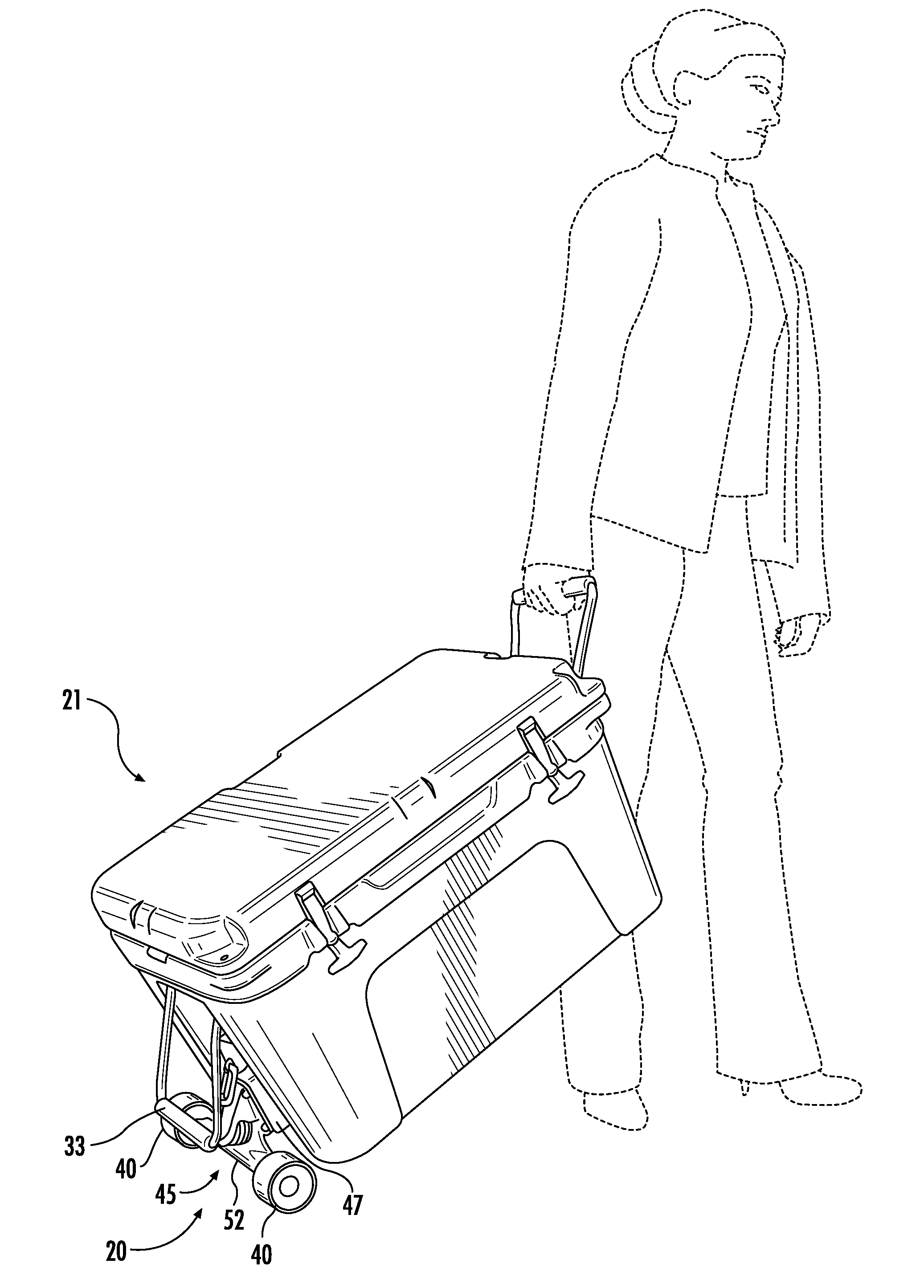
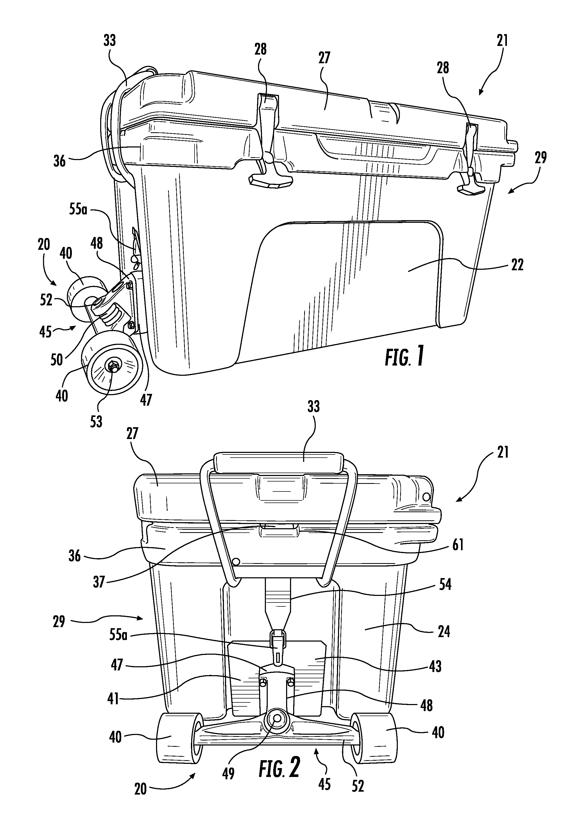
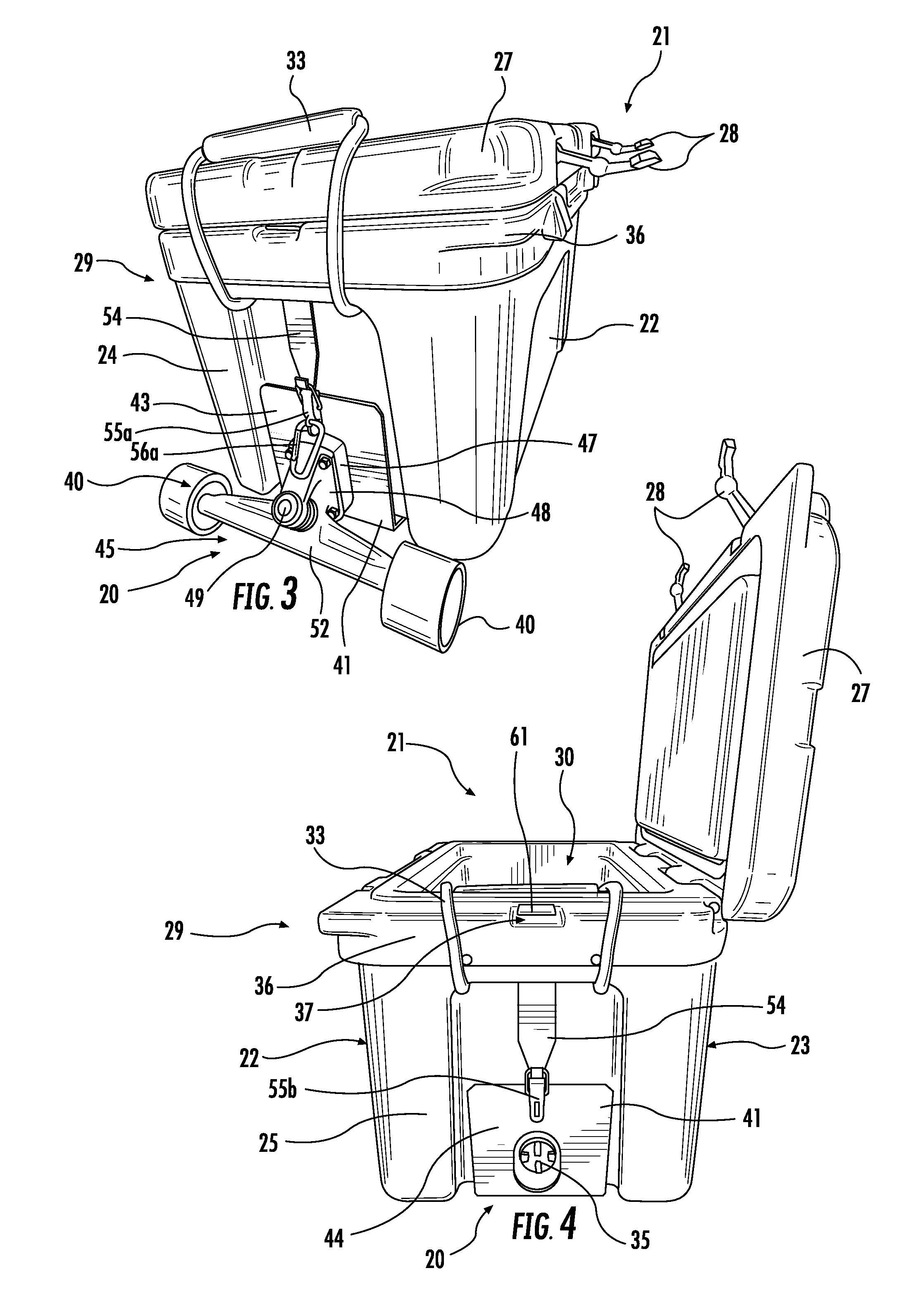
[0031]Referring now to FIGS. 1-11, an exemplary embodiment of a cooler transporting device 20 in accordance with the present disclosure is illustrated. As shown in the accompanying Figures, a cooler transporting device 20 according to the present disclosure generally includes a cooler 21 attached to a U-shaped shoe member 4...


PUM


Abstract

A device for transporting a cooler is disclosed herein. The disclosed cooler transporting device generally comprises a cooler attached to a u-shaped shoe member, the shoe member including a base surface, a first end surface and a second end surface; a wheel attachment member attached to the first end surface of the shoe member; one or more wheels attached to the wheel attachment member; a first locking member attached to the first end surface of the shoe member that couples the first end surface of the shoe member to the cooler; and a second locking member attached to the second end surface of the shoe member that couples the second end surface of the shoe member to the cooler. The disclosed cooler transporting device may be utilized to easily and quickly convert a non-wheeled cooler into a wheeled cooler.

Description

BACKGROUND OF THE INVENTION[0001]1. Field of the Invention[0002]The present invention generally relates to insulated containers such as portable coolers. More specifically, the present invention relates to a device for transporting portable coolers and the like.[0003]2. Description of Related Art[0004]Portable coolers are often used to transport food, beverages and ice to various outdoor activities such as sporting events, picnics, camping trips, etc. When fully loaded with food, beverages and ice, however, the requirement to carry a loaded cooler long distances to a desired location tempers the fun of such activities.[0005]In order to improve the transportability of coolers, some portable coolers are made with wheels. Wheeled coolers typically include a pair of wheels coupled to an axle that extends through an axle aperture formed through a bottom portion of the cooler. Such wheeled coolers usually include recesses in the side insulated walls where the wheels are attached so that t...

Claims


Application Information

Patent Timeline
Patent Type & Authority Patents(United States)
IPC IPC(8): B62B1/22A45C5/14B62B5/00A45C11/20A63C17/00
CPCB62B5/0083A45C5/143B62B1/22A45C11/20B62B2204/06A63C17/0093
Inventor MARTIN, DANIEL TODD
Owner MARTIN DANIEL TODD
Learn More