Foldable transportable structure

a transportable structure and folding technology, applied in special buildings, parkings, buildings, etc., can solve the problems of dimensional limitations that will not allow this structure to physically collapse, roof panels that cannot be completely stretched out to lay flat, and neither roof or wall panels can be completely flat, so as to achieve accurate folding hinge geometry and improve properties. , the effect of long-term dependability

Active Publication Date: 2013-10-15
DIGREGORY VINCENT J
View PDF22 Cites 17 Cited by
  • Summary
  • Abstract
  • Description
  • Claims
  • Application Information

AI Technical Summary

Benefits of technology

[0019]The present invention is a folding transportable shelter with improved properties of: accurate folding hinge geometry, advanced interactive and integrated components that are designed to allow for either transportable or assembled structure configurations; advanced component materials for increased insulation; structural integrity; long-term dependability; built-in flexibility for optional placements of doors, windows or clear openings; and built-in flexibility for choice and use of varying materials and sizes for integrated components.
[0020]It is therefore a primary objective of the present invention to provide a foldable transportable structure that will significantly enhance the quality, functionality, stackable transportability, flexibility and affordability of moveable shelter structures.
[0021]It is another object of the present invention to include in the design a sophisticated geometric folding pattern means that significantly improves the allowance for integration and use of varying component materials, and also significantly improves the interactive complimentary relationships of folding accuracy, necessary clearances, and continual structural contact between adjacent components during the collapse and assembly functions of the unit.
[0022]It is another object of the present invention to include in the design same said sophisticated geometric folding pattern means that remains static, while allowing complete flexibility for: choice of overall structure size; use of any chosen dimension for panel thicknesses and relative connector widths; ability to combine together floor, wall and roof panels that are comprised of different individual thicknesses to obtain varying insulation values; without any of the above impacting the folding and assembly accuracy, or overall capabilities of the structure.
[0023]It is a further object of the present invention to provide specific designed continuous pivot hinge-to-panel connectors, an adjustable door assembly, a leveling foot assembly, a strap conveyance and tie-down assembly, and a flexible fillable bladder bag component to further improve the function, flexibility and use of the structure.
[0025]It is still another object of the present invention to provide a foldable transportable structure that contains the flexibility to be interconnected with additional like units of varying wall thicknesses to make larger structures, and includes removable wall panel sections for in-the-field-flexibility to interchange doors, windows or clear openings to create various configurations for maximum internal occupant flow and use.

Problems solved by technology

Geometric and dimensional limitations will not allow this structure to physically collapse into a stackable configuration as claimed.
The roof panels will not be able to completely stretch out to lay flat when the roof panels are of a long enough dimension to form a gabled configuration, as their combined length when laying flat is much longer than the available length that the wall panels provide when they are in their folded flat configuration.
An attempt to collapse the roof panels into a fully folded flat position will cause the wall panels below to hinge-bind dramatically resulting in neither of the roof or wall panels being able to lay completely flat.
Alternately, when the wall panels are in a completely folded flat position the gable roof panels will not be allowed to fully stretch out and lay flat.
In summary, the designed geometry will not allow full complete collapse of the stacked panels.
This method is limited by the gable end panels being separate components, and the separate fastening components and systems required to erect and / or collapse the unit.
Redeployment and transport of this structure can be accomplished only after a very time consuming and tedious removal of many parts and pieces has been done.
The lack of provisions for a passage opening, door, or other means shown for ingress or egress between the connected units is detrimental to the function and internal occupant flow of the connected units.
Therefore no added value to the user from connecting the units together is recognized, and this may be why this system has not been adopted for large scale use.
This structure is limited in that the gable end panels are separate panels that are hinged to the roof panel.
The erection of the unit will not be manageable by the roof having to carry the added weight of the gable panels during erection of the side walls and roof panels at the same time.
This will be completely unmanageable in the field.
The structure also does not have means for combination of multiple units, or optional door placement locations, or a window to provide ventilation.
This may be why this structure has not been adopted for field use, and is not a presently being manufactured.
This method provides adjustability only to the door frame for installation to variable wall thicknesses, and can only provide one of four possible door swing functions or configurations when installed.
This static configuration does not allow for the potential inversion of the hinge and strike jambs that would be required so that the entire door and frame assembly could be installed in either a right or left hand, or inside or outside, door swing configuration.
This invention has limited use in that is does not offer diversity and the flexibility to be used in both interior and / or exterior applications, and it is not easily reversible or re-installable in the field without the use of tools or separate fasteners that may or may not be available.
This component could not be utilized in a foldable structure as the protrusion will not allow adjacent and connected together wall panels to lay flat against each other when the structure is in a collapsed position.

Method used


Image

  • Foldable transportable structure
  • Foldable transportable structure
  • Foldable transportable structure

Examples


Embodiment Construction

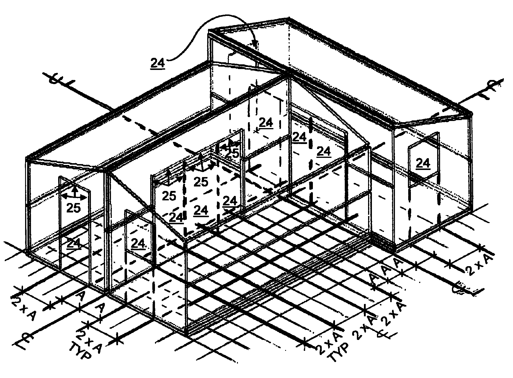
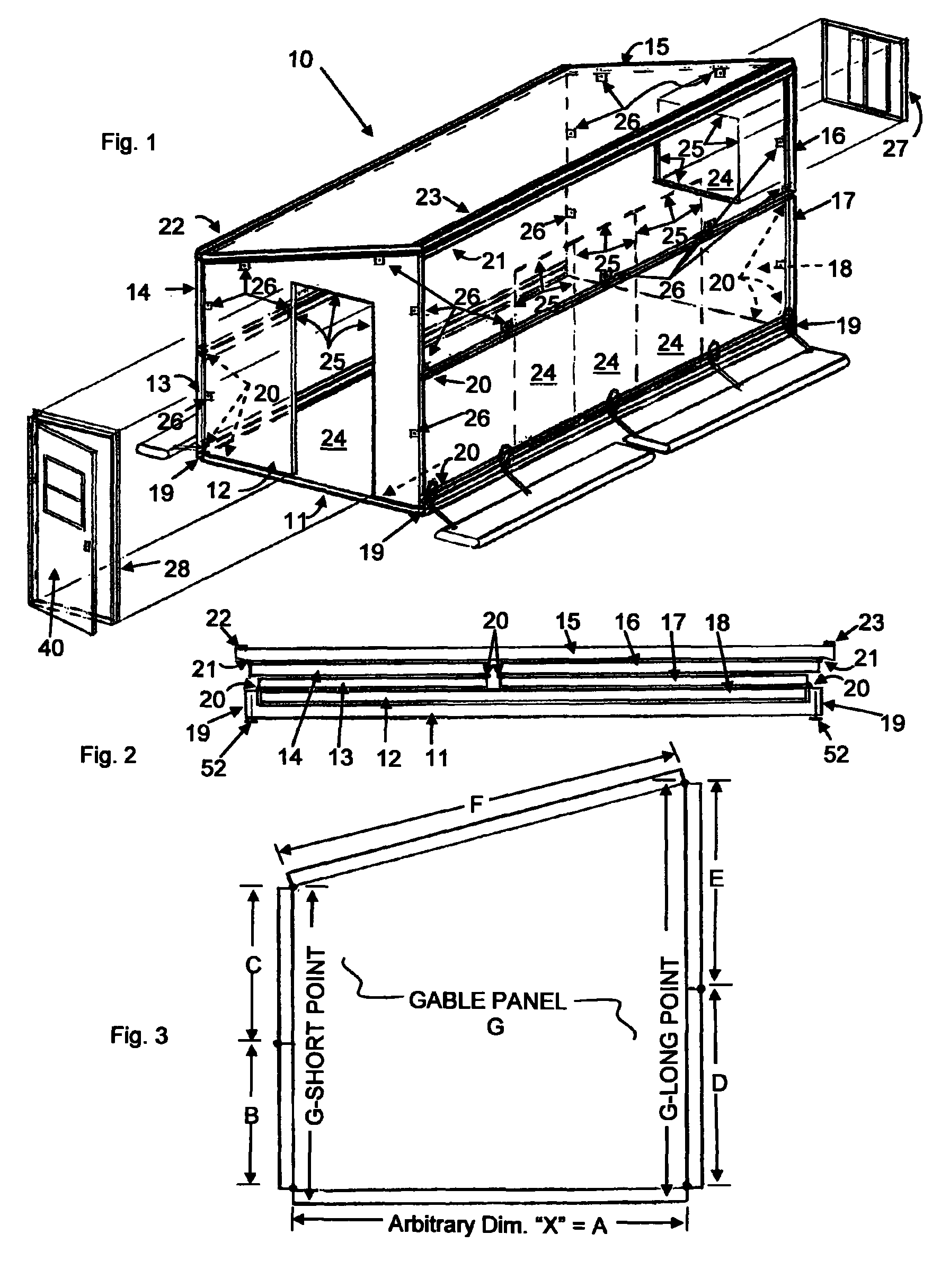
[0045]FIG. 1 shows a perspective view of the best mode contemplated by the inventor of the erected foldable transportable structure 10 according to the concepts of the present invention. As seen by the drawings the foldable transportable structure 10 consist of a series of structural panels and continuous pivot hinge components connected together in a way that allows for either a folding up of the structure into a fully erected configuration as seen in FIG. 1, or a folding down of the structure into a flat fully collapsed configuration for transportable methods as seen in FIG. 2 and FIG. 17.

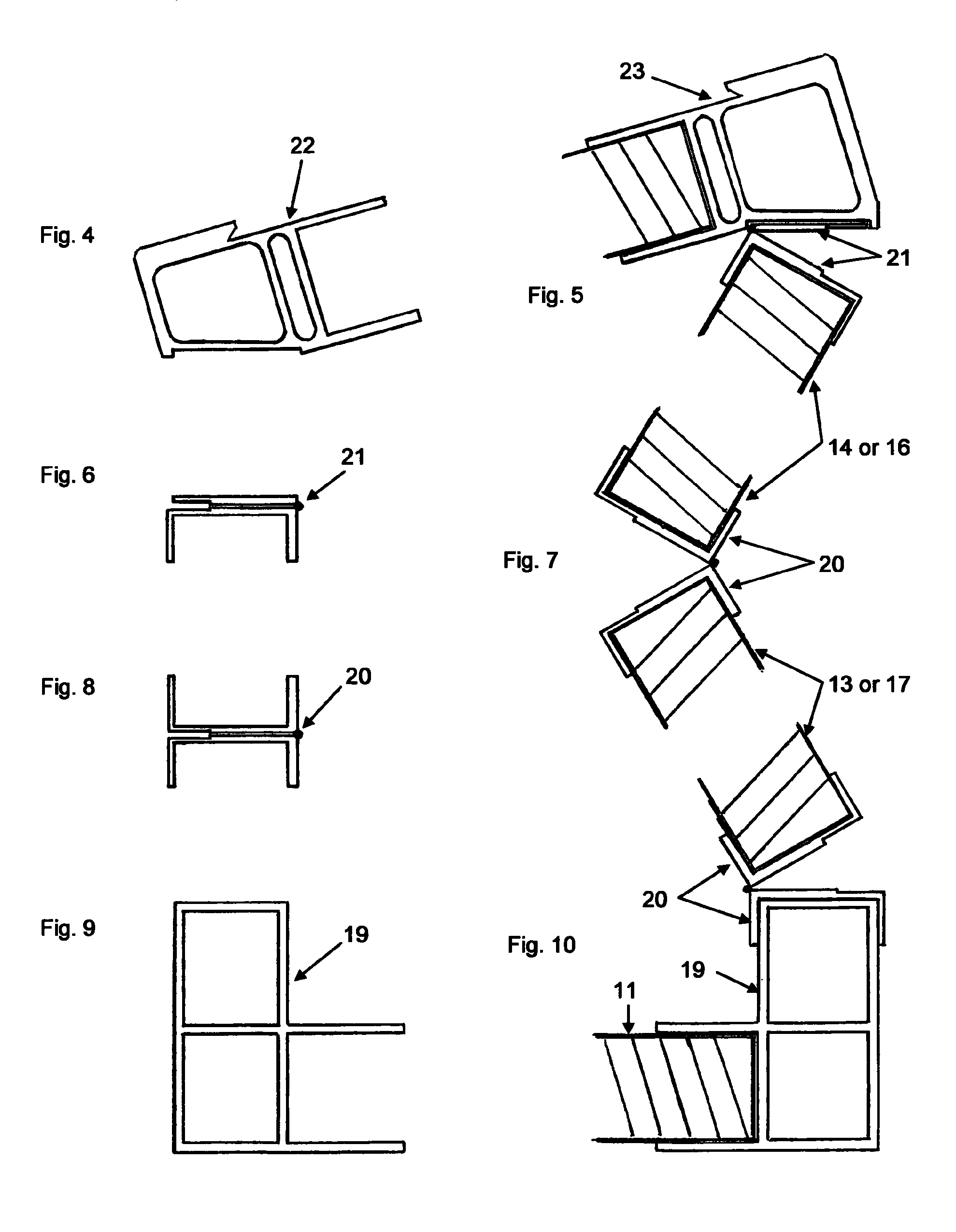
[0046]The foldable transportable structure 10 consists of a single floor panel 11 of which each of its long axis edges are connected to a floor-to-curb panel connector 19, as seen in FIG. 9 and FIG. 10. A continuous pivot hinge wall-to-wall connector 20 is attached between one of the floor-to-curb panel connectors 19 and the short side wall panel 13 as seen in FIG. 10. A continuous pivot hinge wa...


PUM


Abstract

Disclosed is a foldable transportable structure with a three dimensional rectangular shed roof shape having improved component and structural properties, and improved shipping and deployment capabilities. The integrated unique geometric folding pattern means provides enhanced folding accuracy and correct placement of interactive panels during collapse or assembly of the structure, and also greatly increases the flexibility for multiple unit combinations and component materials selection. The folding transportable structure provides a strong, safe, insulated weatherproof structure with a quick setup time, and requires NO tools or separate loose components for assembly.

Description

BACKGROUND OF THE INVENTION[0001]1. Field of the Invention[0002]The present invention relates to a foldable transportable structure that when deployed provides a truly collapsible, transportable, insulated and lightweight structure that is safe, reliable and internationally compliant. Its designed flexibility provides maximum convenience for the following: quick deployment to nearly any geographic location; use of varying component materials and sizes; and interconnectability of single units for multiple unit combinations. The ability of the structure to be air-dropped also allows service to the most remote locations where shelter or facility use is needed.[0003]2. Description of the Prior Art[0004]Typically, supplied conventional structures offer only one or a few of a complete set of required properties that include: an easily erectable configuration for fast field installation; a requirement of NO tools or separate parts and pieces for assembly; a capability for remote deployment...

Claims


Application Information

Patent Timeline
Patent Type & Authority Patents(United States)
IPC IPC(8): E04H1/00
CPCE04B1/3445
Inventor DIGREGORY, VINCENT J.
Owner DIGREGORY VINCENT J
Why Eureka
Try Eureka