
System and method for material weighing and weighing controller

A controller and material technology, applied in the direction of continuous material flow weighing equipment, weighing, instruments, etc., can solve the problem of large weighing errors, differences between the weighed value and the expected weighed value, and materials with high precision requirements Weighing does not meet the requirements and other problems

Inactive Publication Date: 2012-06-13
ZOOMLION HEAVY IND CO LTD
View PDF5 Cites 18 Cited by
  • Summary
  • Abstract
  • Description
  • Claims
  • Application Information

AI Technical Summary

Problems solved by technology

[0003] However, when the screw machine is used for conveying, when the conveying needs to be stopped, the screw machine will continue to run for a period of time due to its large inertia, so the screw machine will continue to deliver materials to the weighing bucket during this period, resulting in the actual weighing value There is a difference between the expected weighing value and the weighing error
[0004] Therefore, in the prior art, if a double butterfly valve is used, the weighing accuracy is difficult to guarantee due to the inability to feed evenly, and if a screw machine is used, there will be a large weighing error. For some materials with high precision requirements (such as dry powder The weighing of mortar) often fails to meet the requirements

Method used


Image

  • System and method for material weighing and weighing controller
  • System and method for material weighing and weighing controller
  • System and method for material weighing and weighing controller

Examples


Embodiment Construction

[0022] Specific embodiments of the present invention will be described in detail below in conjunction with the accompanying drawings. It should be understood that the specific embodiments described here are only used to illustrate and explain the present invention, and are not intended to limit the present invention.

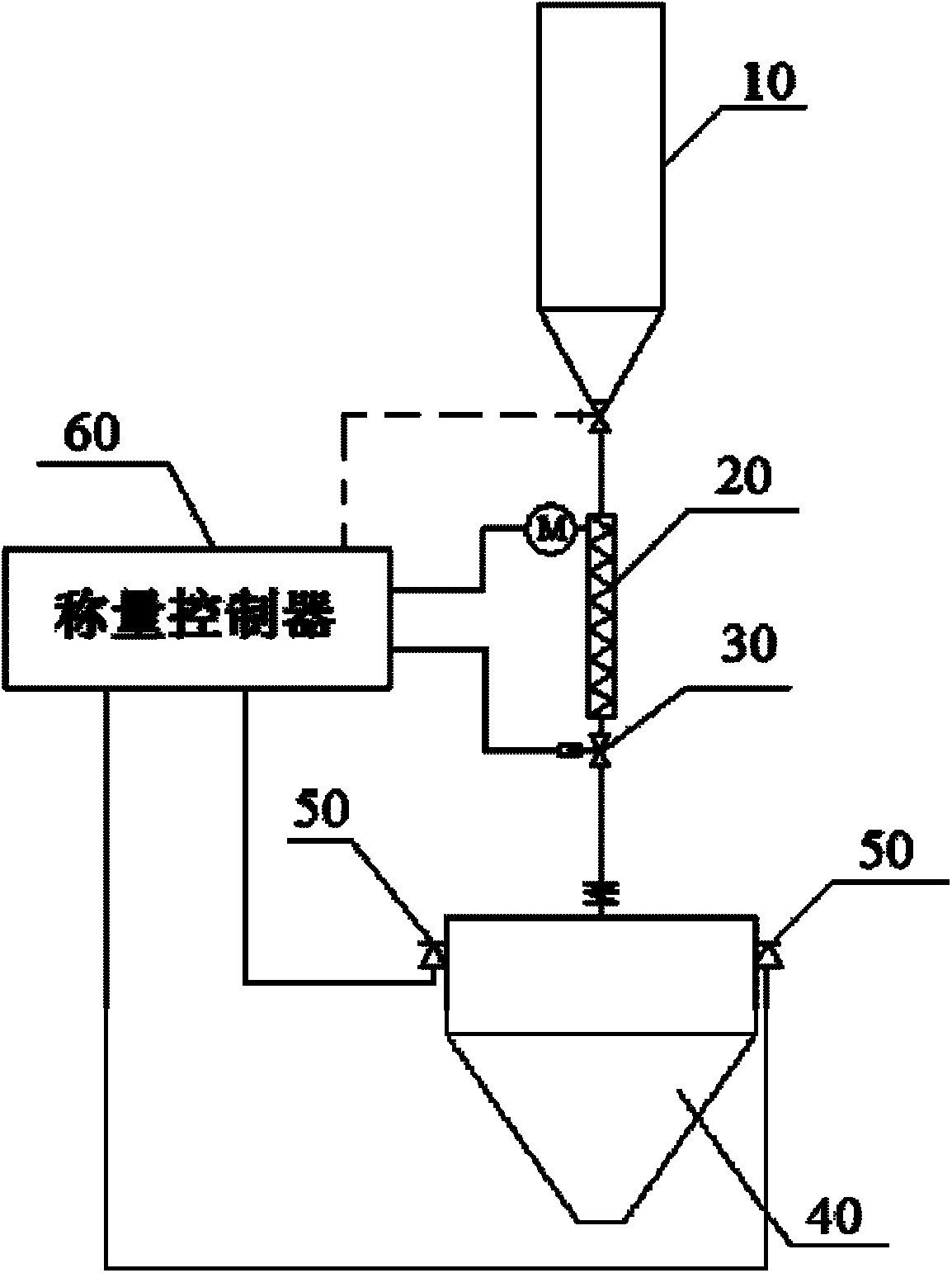
[0023] Such as figure 1 As shown, the material weighing system provided by the present invention is firstly described. The system includes a weighing hopper 40, a screw machine 20, a butterfly valve 30 and a load cell 50, the load cell 50 is used to detect the real-time weight of the material in the weighing hopper 40, and the delivery outlet of the screw machine 20 is located at the opening of the weighing hopper 40 Above, the butterfly valve 30 is located at the delivery outlet of the screw machine 20, and the delivery outlet of the screw machine 20 is closed when the butterfly valve 30 is closed.

[0024] exist figure 1 Among them, the delivery inlet of th...


PUM


Abstract

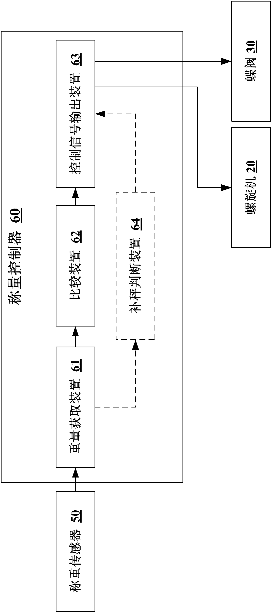
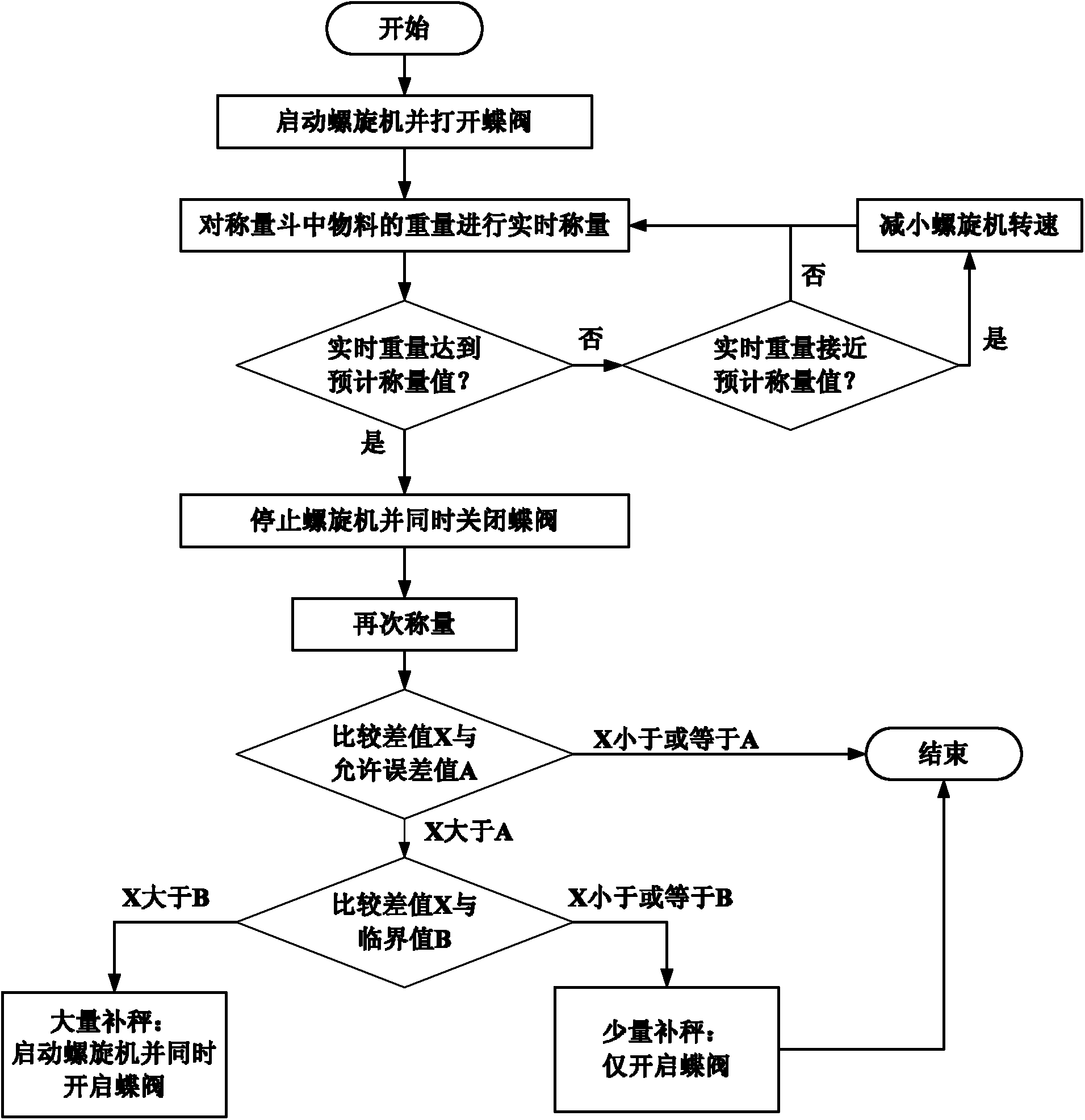
The invention discloses a system and a method for material weighing and a weighing controller. The material weighing system comprises a weighing hopper (40), a spiral conveyor (20), a butterfly valve (30) and a weighing sensor (50). A conveying outlet of the spiral conveyor (20) is located above an opening of the weighing hopper (40), the butterfly valve (30) is located at the conveying outlet of the spiral conveyor (20), and when the butterfly valve (30) is closed, the conveying outlet of the spiral conveyor (20) is sealed. The weighing controller (60) comprises a weight obtaining device (61), a comparison device (62) and a control signal output device (63), wherein the weight obtaining device (61) is used for receiving a signal for indicating weight of materials in the weighing hopper (40) and obtaining real-time weight of the materials from the signal, the comparison device (62) is used for comparing the real-time weight of the materials with a predicting weighing value, and the control signal output device (63) is used for simultaneously outputting a control signal for controlling the stopping of the spiral conveyor (20) and a control signal for closing the butterfly valve (30) when the comparison result of the comparison device (62) is that the real-time weight reaches the predicting weighing value. When the materials reach a certain value, the spiral conveyor and the butterfly valve can be closed simultaneously, thereby obtaining double advantages of good conveying effect of the spiral conveyor and fast response of the butterfly valve.

Description

technical field [0001] The invention relates to the field of material weighing, in particular to a material weighing system, a material weighing method and a weighing controller used in the material weighing system. Background technique [0002] At present, there are generally two ways to weigh the weight of materials. One is to use double butterfly valves for transportation, that is, double butterfly valves are installed at the end of the transportation pipeline. Open both butterfly valves to achieve the maximum delivery channel, and then close one of the butterfly valves when the weighing value is close to the expected weighing value, so that the material delivery outlet becomes smaller, so as to control the weighing accuracy, and finally close the other A butterfly valve. However, this method completely relies on the gravity of the material when conveying the material. Therefore, for the powder with poor fluidity, uniform feeding cannot be achieved, which brings inconve...

Claims


Application Information

Patent Timeline
Patent Type & Authority Applications(China)
IPC IPC(8): G01G11/08
Inventor 齐华王子劼万博邓小梅
Owner ZOOMLION HEAVY IND CO LTD
Learn More