Truck sports rack

a truck and rack technology, applied in the field of truck sports racks, can solve the problems of increasing the difficulty of mounting and demounting the rack from the truck, increasing the overall weight of the rack, and having an adverse effect on the handling of the truck on which it is mounted, so as to achieve easy disassembly and assembly in pieces, reduce the overall cost of the rack, and facilitate the effect of adaptability

Active Publication Date: 2007-04-03
IND DISENADORA DE AUTOPARTES S A DE
View PDF40 Cites 17 Cited by
  • Summary
  • Abstract
  • Description
  • Claims
  • Application Information

AI Technical Summary

Benefits of technology

[0007]The present invention provides a truck sports rack that can be easily dissembled in pieces for shipment and re-assembled such that it may be mounted on a truck. The sports rack is assembled of a plurality of lightweight, standardized components wherein the sports rack is of modular construction such that it may be easily adapted to fit a wide variety of truck beds. In addition, such modularity lowers the overall cost of the sports rack and enhances its transportability and storability. The sports rack comprises a pair of frame members and a plurality of channel lengths extending horizontally between the frame members. Each of the frame members and the channel lengths is perforated with a plurality of lightening holes for hanging or securing various objects. The lightening holes further reduces the overall weight of the sports rack such that mounting and demounting of the sports rack may be readily facilitated with minimal effort.
[0008]The sports rack comprises a pair of frame members and a plurality of elongate channel lengths extending between the frame members. Truck beds of many trucks typically have a front wall, a rear tail gate, and a pair of elongate side walls extending therebetween with a bed rail extending about a perimeter of the truck bed. The frame members may be configured as two substantially vertically disposed frame members that are respectively secured to the side walls of the truck bed. The channel lengths and the frame members are configured as horizontal members with a generally shallow U-shaped cross section to increase stiffness and rigidity of the channel lengths. The lightening holes may be formed in each one of the channel lengths and the frame members in order to reduce the overall weight of the sports rack.
[0011]Each of the uprights, the cross channels, and the channel lengths is configured as a substantially flat elongate panel having side flanges extending from opposing edges to form a shallow U-shaped configuration. The corner pieces may be provided in a curved configuration in order to provide a smooth load path between the uprights and the cross channels as well as to improve the overall aesthetics of the sports rack. End plates on each end of the corner pieces may include corner piece end plate holes. Each of the uprights and the cross channels also include a pair of end plates at opposing ends with holes formed therethrough. Mechanical fasteners may be extended through the holes in order to interconnect the cross channels, corner pieces and uprights.

Problems solved by technology

Unfortunately, none of these racks are easily mountable due to the relatively large number of mounting components and the large number of fasteners to interconnect such mounting components.
In addition, most of these racks are constructed of relatively heavy bar, tubing or frame members which increases the difficulty in mounting and demounting the rack from the truck.
Furthermore, the overall weight of such racks may have an adverse effect on handling of the truck on which it is mounted.
Such truck racks suffer from several deficiencies that detract from their overall utility.
For example, truck racks that are provided as a welded construction result in a relatively large structure.
Unfortunately, such truck racks must be provided in a relatively large variety of sizes in order to accommodate the wide variety of truck bed geometries that are available from the various truck manufacturers.
In addition, the cost of shipping such truck racks from the manufacturer to retailers is relatively high due to the bulkiness of such truck racks.
Furthermore, the cost of storing the truck racks and displaying the truck racks is also relatively large due to the large amount of space required.

Method used


Image

  • Truck sports rack
  • Truck sports rack
  • Truck sports rack

Examples


Embodiment Construction

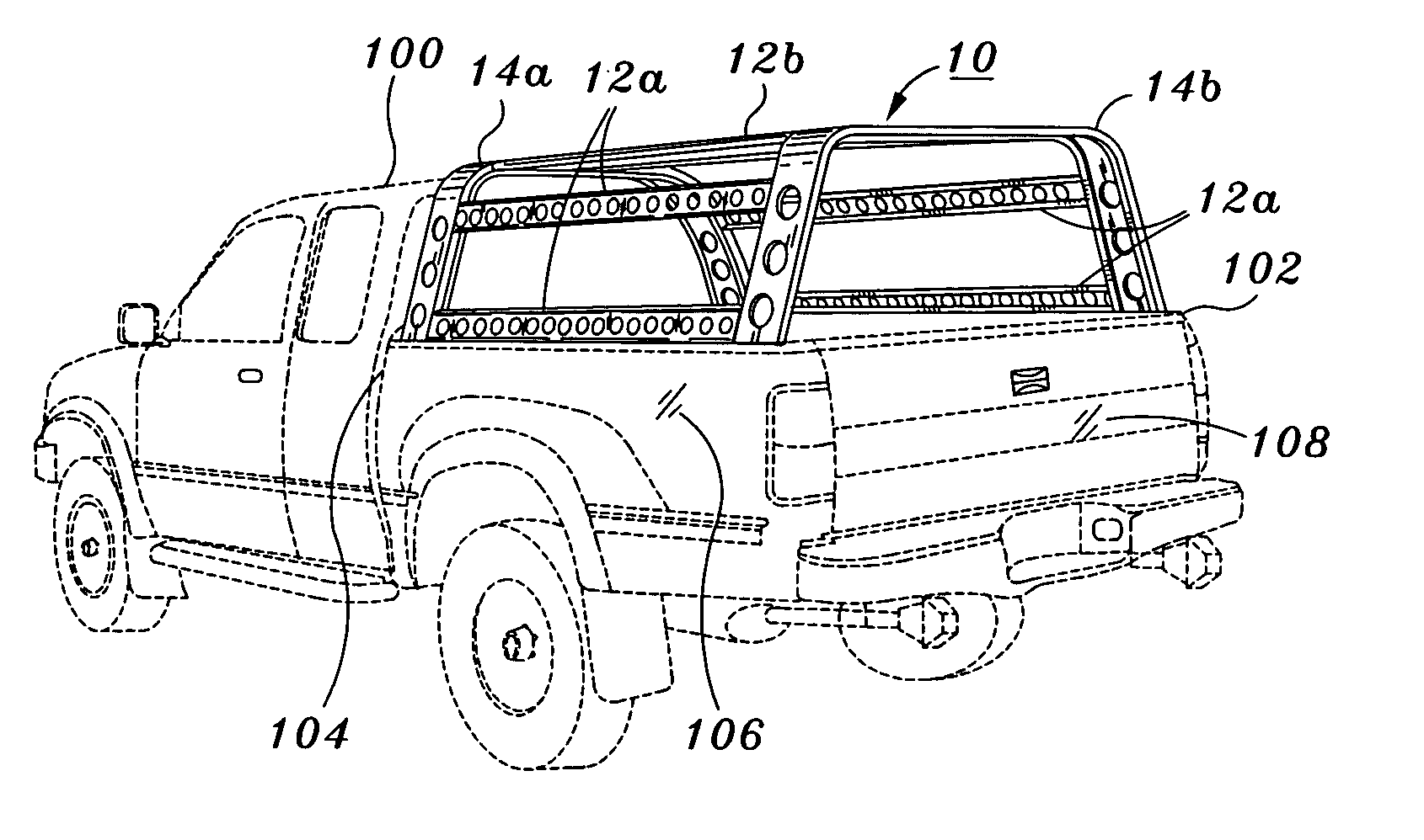
[0025]The present invention provides a sports rack 10 for a truck 100 such as a pickup truck 100 as shown in FIG. 8. As will become apparent in the description that follows, the rack has a modular construction allowing its fitment to a wide variety of trucks 100 having truck beds 102 of varying geometry. Furthermore, the rack is relatively lightweight such that it may be easily assembled, mounted on and demounted from the truck 100. The truck bed 102 may have a front wall 104, a rear tail gate 108, and a pair of elongate side walls 106 extending therebetween. The front wall 104 and side walls 106 may each include a bed rail 110 extending along a perimeter of the truck bed 102. The sports rack 10 may be mounted on the side bed rails 110 of the pickup truck 100 by various mechanisms that will be described in detail below.

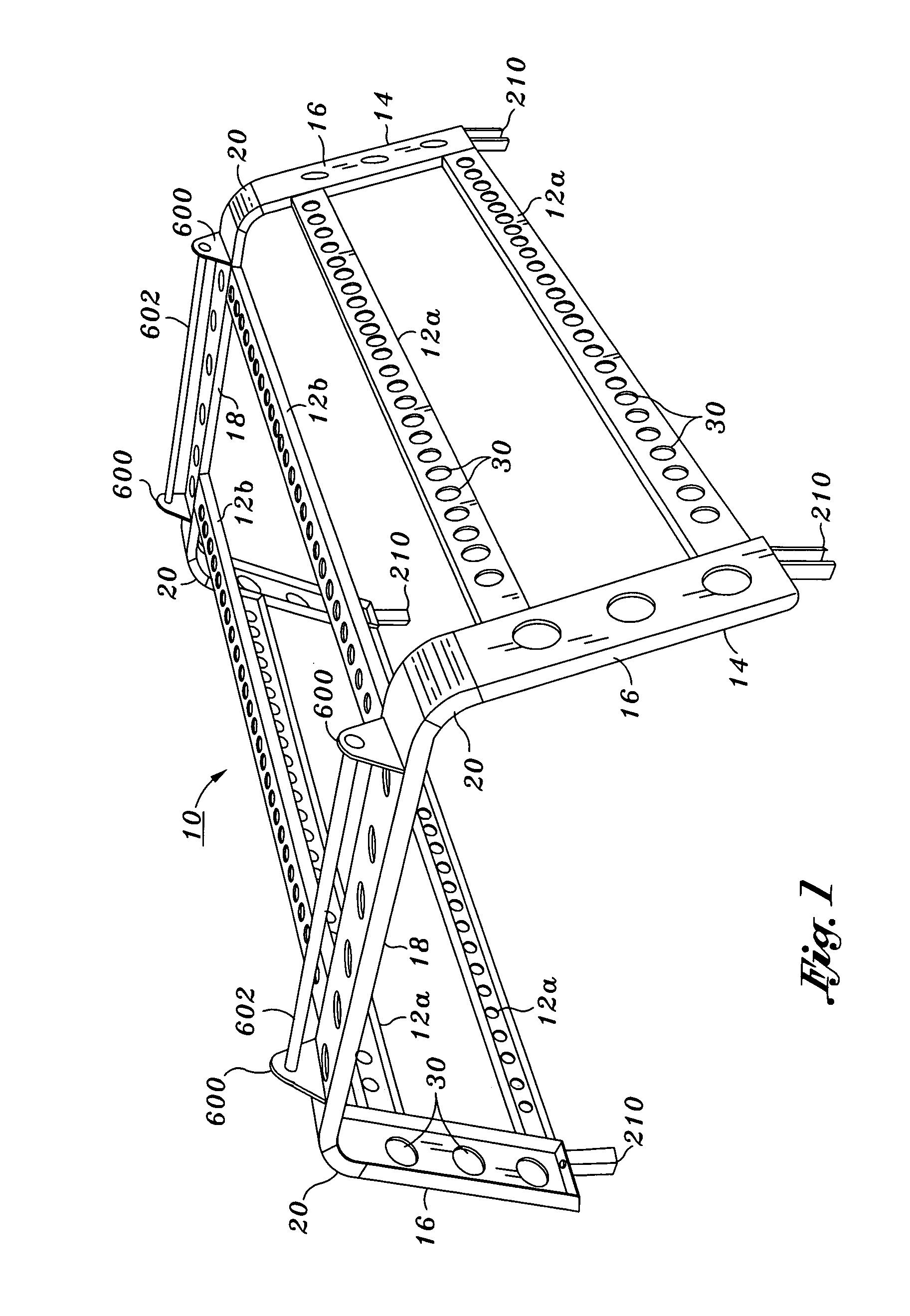
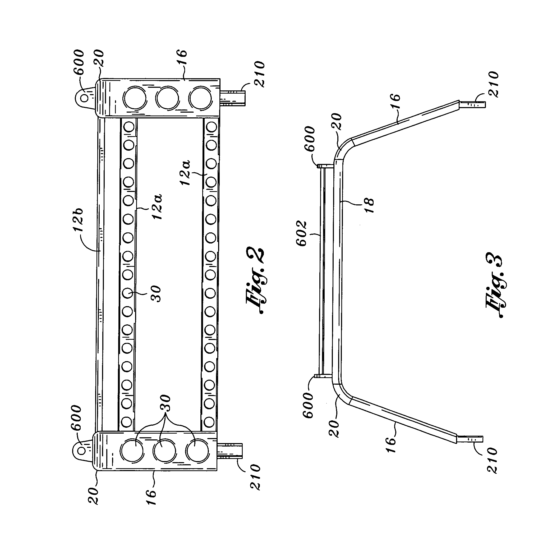
[0026]The sports rack 10 comprises a pair of frame members 14 and a plurality of elongate channel lengths 12 extending between the frame members 14. The frame members...


PUM

PropertyMeasurementUnit
lengthsaaaaaaaaaa
channel lengthsaaaaaaaaaa
lengthaaaaaaaaaa

Abstract

Provided is a sports rack configured to be mounted on a truck bed. The truck bed may have a front wall, a rear tail gate and a pair of elongate side walls extending therebetween. Each one of the side walls may have a bed rail. The sports rack comprises a front frame member, a rear frame member and a plurality of channel lengths. The front frame member is disposed adjacent the front wall and extends between the side walls. The rear frame member is disposed over the rear tail gate and also extends between the side walls. The plurality of channel lengths extends horizontally between the front and rear frame members. Each of the front and rear frame members comprises a pair of upright end plates that may be used to mount the sports rack on the bed rails.

Description

CROSS-REFERENCE TO RELATED APPLICATIONS[0001]Not ApplicableSTATEMENT RE: FEDERALLY SPONSORED RESEARCH / DEVELOPMENT[0002]Not ApplicableBACKGROUND OF THE INVENTION[0003]The present invention relates in general to a truck sports rack and, more particularly, to a truck sports rack that can be dissembled in pieces for shipment and quickly reassembled for such that it may be mounted on a truck.[0004]Various types of truck racks have been developed for protecting goods or cargo carried on a truck bed of a truck. Conventional truck racks are either permanently mounted on a bed rail of a pickup truck or removably mounted on the truck using complex mounting hardware. For example, in published U.S. patent application 2003 / 0164621, U.S. Pat. No. 6,347,731, U.S. Pat. No. 5,927,782, racks disclosed therein each require specialized mounting mechanisms that comprise several elements for mounting the rack to the bed rail of a pickup truck. Unfortunately, none of these racks are easily mountable due t...

Claims


Application Information

Patent Timeline
Patent Type & Authority Patents(United States)
IPC IPC(8): B60P3/00B60R9/00
CPCB60R9/00Y10T29/49622
Inventor STORER, RON D.
Owner IND DISENADORA DE AUTOPARTES S A DE
Why Eureka
Try Eureka