
Lighting Control Console For Controlling A Lighting System

a technology lighting systems, applied in the field of lighting control consoles for controlling lighting systems, can solve the problems of intransparency and the drawback of known display units intended for lighting control consoles, and achieve the effect of more intuitive operation of the operating elements

Active Publication Date: 2012-01-05
MA LIGHTING TECH
View PDF9 Cites 19 Cited by
  • Summary
  • Abstract
  • Description
  • Claims
  • Application Information

AI Technical Summary

Benefits of technology

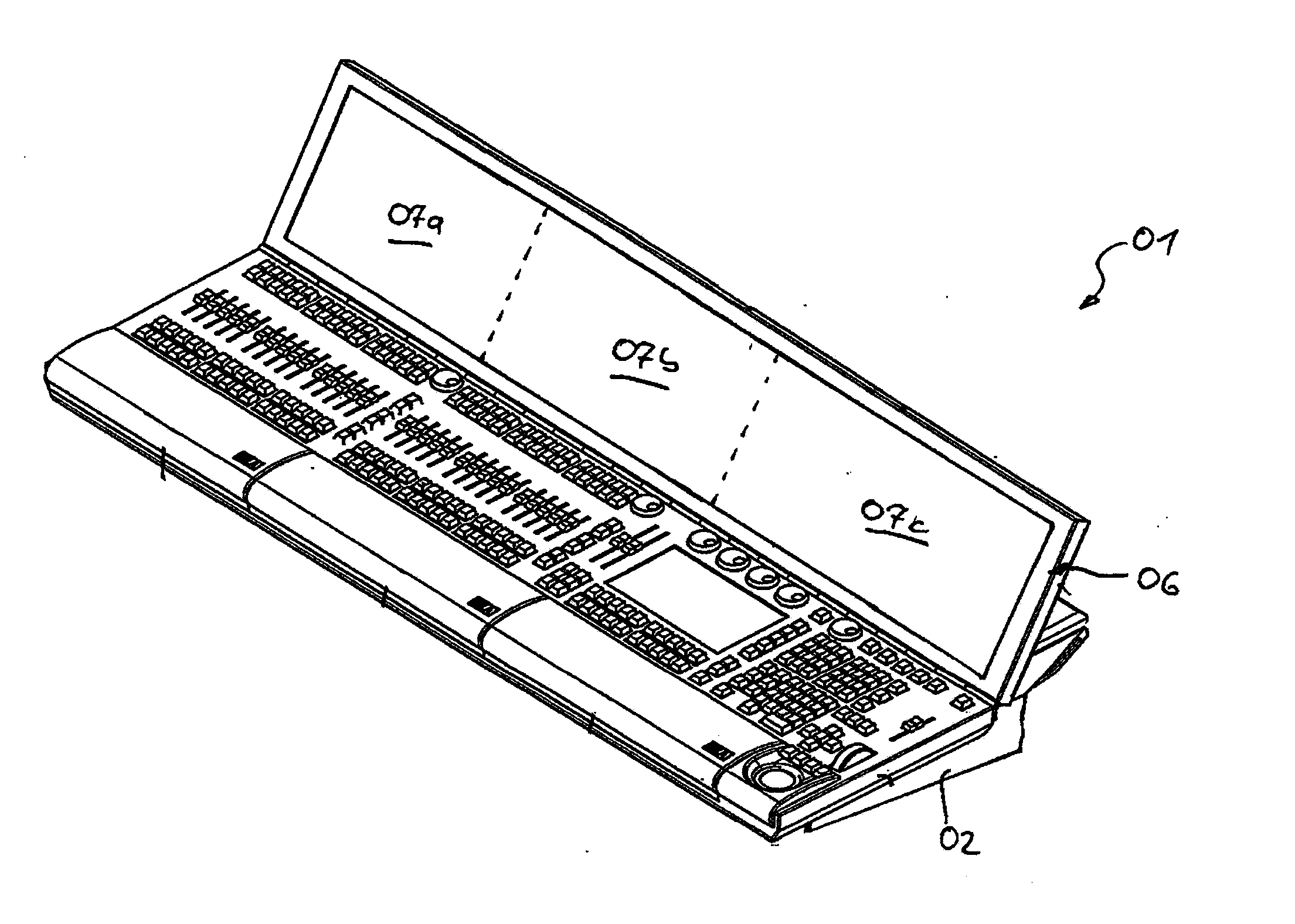
[0009]By way of the inventive utilization of a display unit that can be switched between a transparency mode and a display mode, the operator is provided with the option to observe the regions located behind the display surface, for instance a stage with the lighting devices arranged thereon, through the display surface upon activation of the transparency mode. By switching the display unit into the display mode, the operator in turn is provided with the option to cause graphical elements for operating the lighting control console to be displayed on the display surface. Hence, in other words, due to the aspect that the operator is provided with the option to switch the display unit into a transparency mode, the operator is no longer required to get up or else to change his / her seating position in order to be able to look past the display unit to observe the field of vision lying behind the same.
[0014]As an alternative to utilizing an electro-chromatic glass, the projection surface may equally be made of a transparent glass carrier having a transparent film disposed thereon, wherein this film in turn includes a plurality of holographic optical elements (HOE). The holographic optical elements disposed on the transparent film cause a deflection of light, so that the light beam emitted from the projector, which is incident on the holographic optical element, is deflected at a certain angle towards the observer. Light, such as in particular ambient light, that is incident on the holographic optical elements at a different angle is not deflected towards the observer and thusly cannot be spotted on the part of the observer. Thus, by utilizing the holographic optical elements, it is possible to create transmitted-light projection screens suitable for use in daylight.
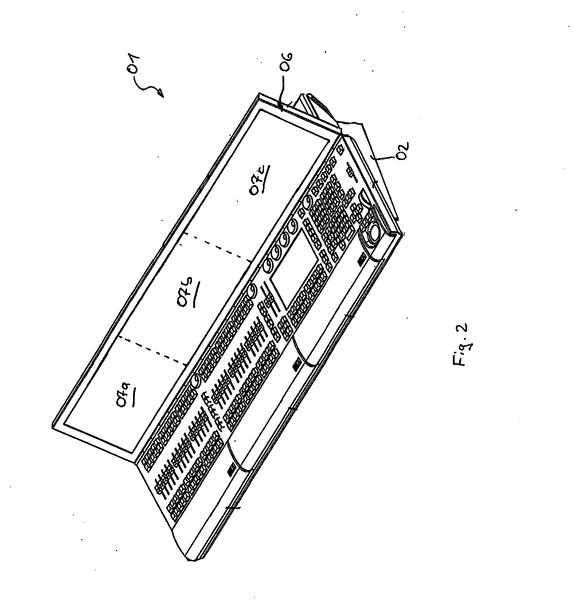
[0015]In order to provide the operator with the option of adjusting the display unit to his / her individual needs, it is especially advantageous if the display unit is mounted at the housing so as to be pivotable about a swivel axis and can be pivoted between a swiveled-back rest position and a swiveled-up operating position, in particular in a continuous fashion. By means of arranging the display unit in the rest position, it is in particular possible to enhance the transportability of the lighting control console. In the rest position, the display unit may fit into the surface of the top of the housing, for instance in a manner complementary in shape. By means of swiveling the display unit upwards into the operating state, conversely, a particularly convenient angle of view on the part of the operator is then enabled for the display unit, since the display unit extends to the top of the housing, for instance at a steep angle. For the purpose of the constructional configuration of the pivotable mounting of the display unit, the display unit may be fastened for instance at a pivotably-mounted carrier element of the housing.
[0016]In the simplest embodiment of the pivotable mounting of the display unit, the swiveling motion is manually transferred to the display unit by the operator. For the purpose of further enhancing the operating convenience, however, provision may equally be made for a drive unit that is engaged between housing and display unit and that enables motor-driven displacement of the display unit between rest position and operating position.
[0018]In the light of the aspect that the utilization of a transmitted-light projection for displaying the graphical elements presupposes a specific angle to be maintained between projector and projection surface, it is especially advantageous if the projector for projecting the graphical representation is disposed at a portion of the drive unit, in particular at the gear rim, for motor-driven displacement of the display unit. In this way, it is possible to equally displace the projector synchronously thereto upon actuation of the display unit, so that the angle between projector and display surface in each case remains the same.
[0020]Moreover, it is especially advantageous if the operating elements can be displayed on the display surface in a three-dimensional representation, in order to enable a more intuitive operation of the operating elements.

Problems solved by technology

These known display units intended for lighting control consoles are afflicted with the drawback of intransparency, since during utilization of the lighting control console, particularly during programming of the lighting control console, the operator is frequently required to alternately turn his / her eyes to the lighting system to be programmed, for instance a stage lighting, and to the display surface at the display unit.

Method used


Image

  • Lighting Control Console For Controlling A Lighting System
  • Lighting Control Console For Controlling A Lighting System
  • Lighting Control Console For Controlling A Lighting System

Examples


Embodiment Construction

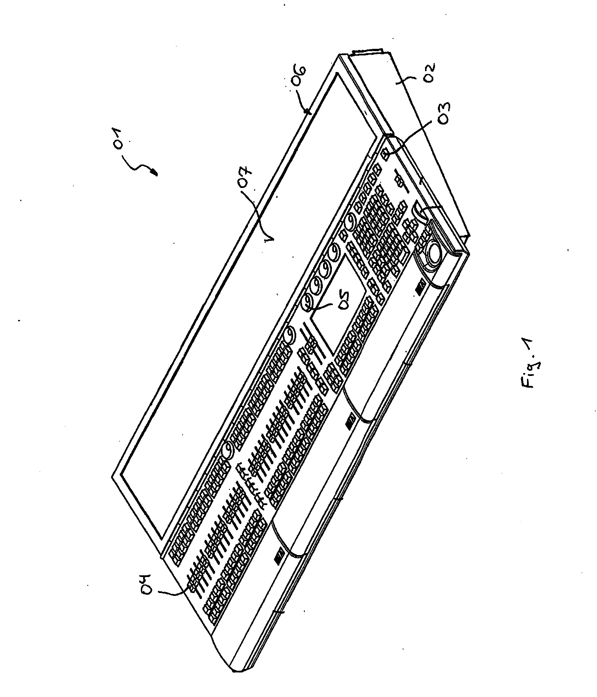
[0027]FIG. 1 shows a lighting control console 01 for controlling a complex lighting system. Here, the housing 02 contains a plurality of digital processors and digital memories for generating, transmitting and storing digital adjustment commands. A large number of control elements, particularly buttons 03, slide controls 04 and rotary knobs 05, are arranged on the top of the housing 02. The lighting control console 01 is likewise equipped with a display unit 06 pivotably mounted at the housing 02. The display unit 06 here comprises a display surface 07 that can be switched between a transparent transparency mode and an intransparent display mode. In this context, the display surface 07 of the display unit 06 is formed by a projection unit, i.e. the display surface 07 serves as projection surface, a transmitted-light projector 08 (see FIG. 4) projecting graphical elements onto the rear side thereof. In order to make it possible to cover the entire surface of the display unit 06, here...


PUM


Abstract

A lighting control console for controlling a lighting system, wherein digital adjustment commands are generated in the lighting control console and can be transmitted to the lighting devices of the lighting system via data connections includes at least one digital processor and at least one digital memory for generating, managing and storing the adjustment commands, and at least one display unit. Graphical elements can be displayed graphically for the operator at the display unit on a display surface. The display unit is made of an at least partially transparent material in the region of the display surface, wherein the display unit can be switched between a transparency mode and a display mode, and wherein the display unit (06) is partially transparent upon activation of the transparency mode in the region of the display surface and enables the operator to look through the display surface. The display unit enables the graphical representation of graphical elements on the display surface for the operator upon activation of the display mode in the region of the display surface.

Description

CROSS REFERENCE TO RELATED APPLICATION[0001]Not applicable.STATEMENT REGARDING FEDERALLY SPONSORED RESEARCH OR DEVELOPMENT[0002]Not applicable.FIELD OF THE INVENTION[0003]The invention concerns a lighting control console for controlling a lighting system, wherein digital adjustment commands are generated in the lighting control console and can be transmitted to the lighting devices of the lighting system via data connections. The lighting control console includes at least one digital processor and at least one digital memory for generating, managing and storing the adjustment commands, and at least one display unit. Graphical elements can be displayed graphically for the operator at the display unit on a display surface.BACKGROUND OF THE INVENTION[0004]Generic lighting control consoles serve the purpose of controlling lighting systems such as are used for example in theaters or else on concert stages. These lighting systems typically include a plurality of lighting devices, for inst...

Claims


Application Information

Patent Timeline
Patent Type & Authority Applications(United States)
IPC IPC(8): G06F17/00
CPCG06F1/1616H05B37/029H05B37/0245G06F1/1643H05B47/155H05B47/175
Inventor ADENAU, MICHAELCORDES, HARTMUT
Owner MA LIGHTING TECH
Learn More