Fluid sampling probe with vibration dampening

a sampling probe and vibration dampening technology, applied in the field of fluid sampling probes with vibration dampening, can solve the problems of poorly designed sampling probes bending or breaking off in the flowing gas stream, complicated construction and operation, metal embrittlement, etc., to reduce the forces and deflections of the probe, reduce the effect of vortex shedding and oscillations

Active Publication Date: 2015-12-01
MAYEAUX HLDG
View PDF11 Cites 13 Cited by
  • Summary
  • Abstract
  • Description
  • Claims
  • Application Information

AI Technical Summary

Benefits of technology

[0036]Accordingly, the outer diameter of the probe of the preferred embodiment of the present invention is threaded. In the fluid stream, the threaded portion of the probe provides spiral ridges which have been found to function as helical strakes when in contact with the fluid stream, which has been found to effectively act as aerodynamic stabilizers, which can reduce the forces and deflections of the probe due to vortex shedding. Helical strakes in other applications outside of analytical sampling have been used in various iterations, for example, to protect stacks and towers from damage caused by oscillations due to wind induced vortex shedding. In a similar manner, these spiral ridges can act to control, reduce, or even possibly eliminate the formation of the oscillations.
[0037]The preferred embodiment of the present invention's concept of providing sp

Problems solved by technology

Additionally sensors, such as pressure and temperature sensors and corrosion coupons often require insertion into pressurized fluid streams.
The Welker patents describe probes requiring valving and pneumatic or hydraulic cylinders which complicates their construction and operation.
Another common problem associated with the use of sampling probes, sensors or the like in a high velocity fluid stream (or even lower velocity fluid streams, depending upon the structure of the probe and density of the fluid) relates to the phenomenon of resonant vibration induced in the probe i

Method used


Image

  • Fluid sampling probe with vibration dampening
  • Fluid sampling probe with vibration dampening
  • Fluid sampling probe with vibration dampening

Examples


Embodiment Construction

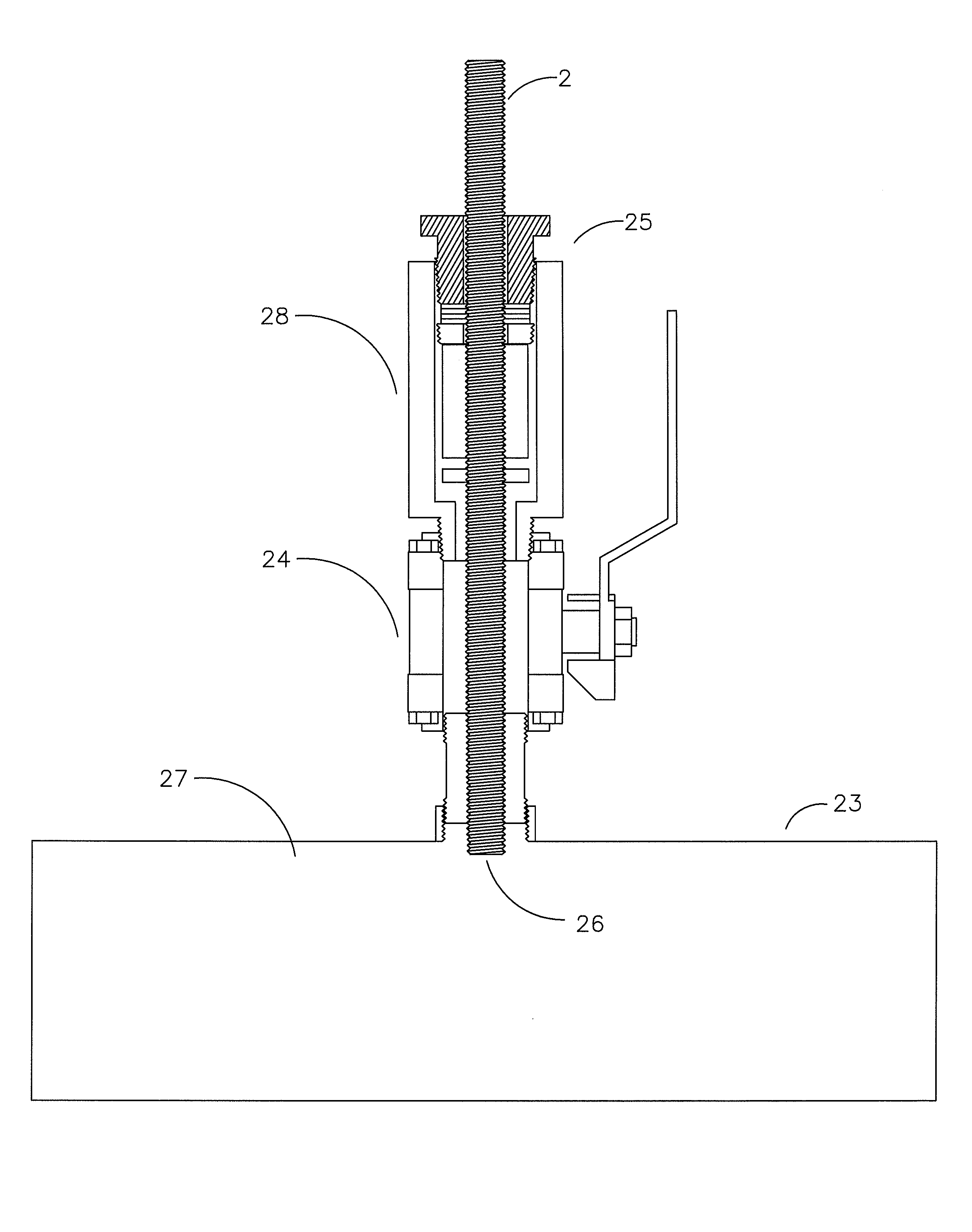
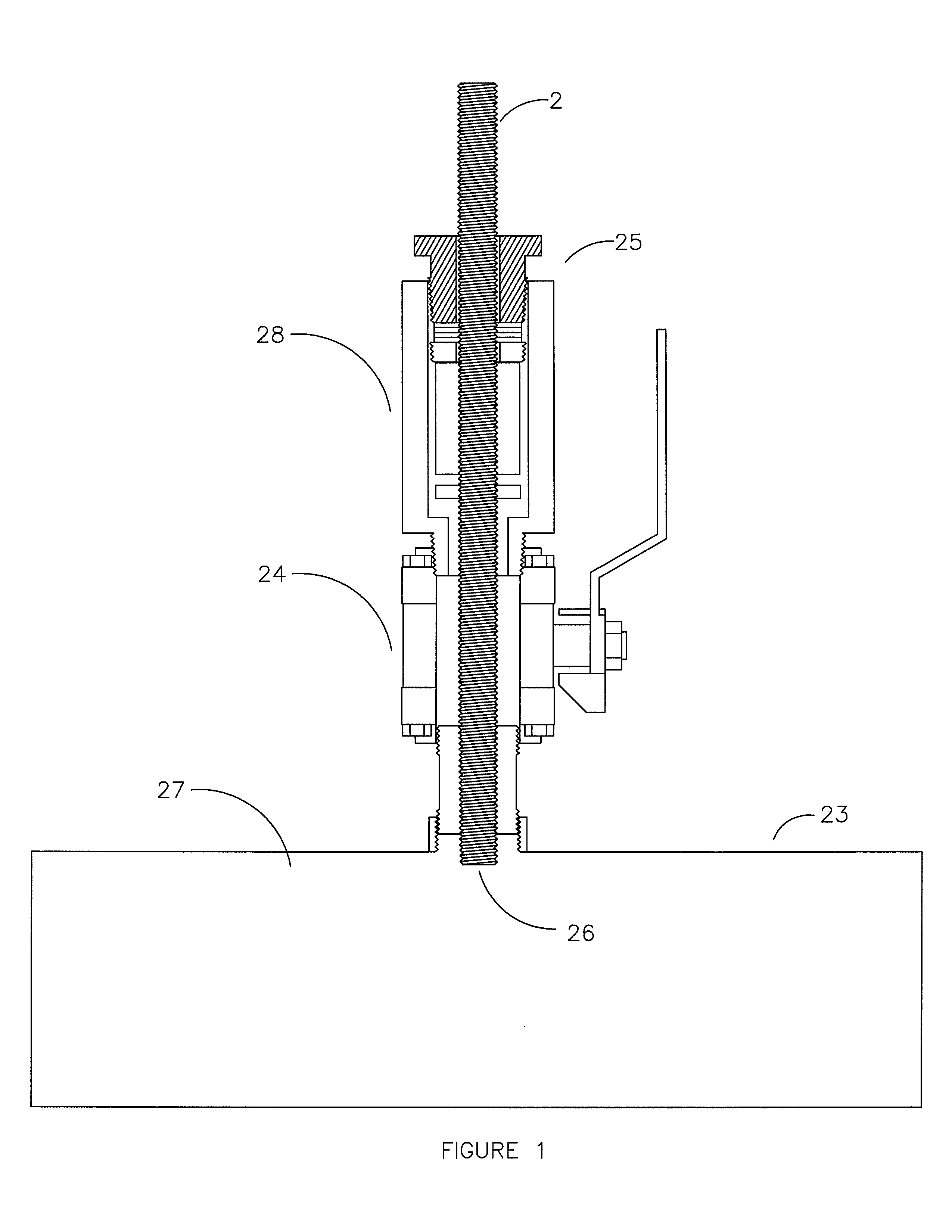
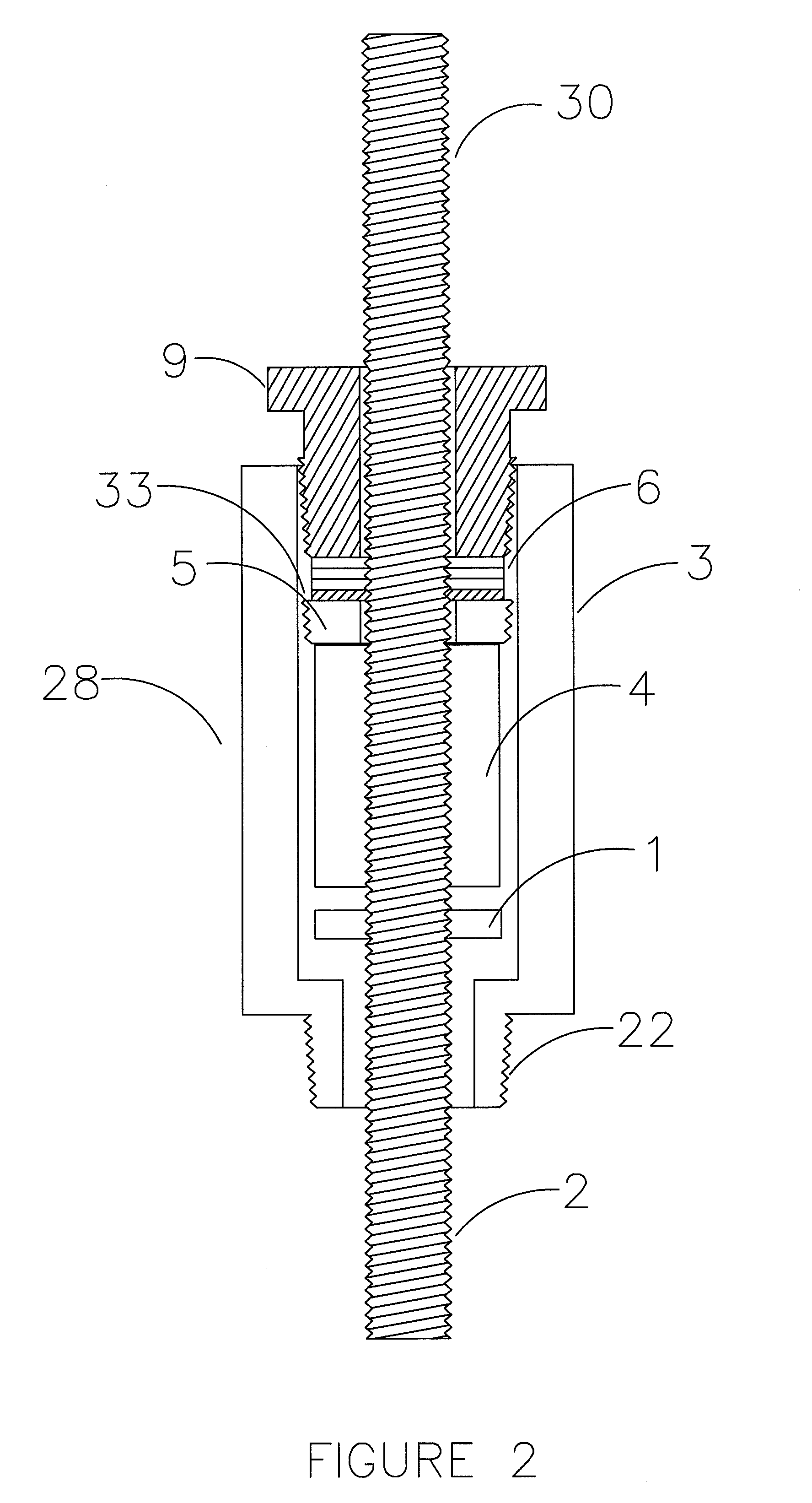
[0046]The present invention comprises a probe shaft having external threads which, when rotated, is inserted to or retrieved from a pressurized fluid source through via a threaded seal and a threaded female member. The probe may be configured to extract a fluid sample, insert a sensor or corrosion coupon, or perform a variety of tasks requiring insertion into a pressurized fluid.

[0047]Unlike prior art which utilizes a threaded member to force a smooth walled rod or probe into a pressurized fluid container through a seal, the current invention utilizes a seal around the threaded area of the threaded member. This significantly simplifies the construction and reduces the risk of the probe blowing out of the seal.

[0048]In addition, the present invention provides the additional benefit of enhanced mechanical dampening via the design and configuration of seals and inserts, providing non-rigid engagement to support the probe along its length, using the packing gland to effectively isolate ...


PUM


Abstract

A system for insertion of a probe into a pressurized fluid stream by means of a threaded body formed to engage an elastomeric seal employed to form a fluid barrier thereabout. The present invention contemplates a system which effectively lessens resonance vibration effects and associated damage resulting there from in fluid sampling probes operating in high velocity fluid streams and the like, utilizing mechanical dampening properties associated with its seal(s) and insert(s), forming non-rigid attachment to support the length of the probe in a manner which facilitates resonance absorption and dampening, so as to lessen associated vibration/oscillation in the system. The threaded body forms, in effect, helical strakes to facilitate aerodynamic stabilization and reduce oscillations/vibration, as well as reduce force and deflection caused by high velocity fluid flow passing thereby.

Description

BENEFIT CLAIM[0001]The present application is a continuation-in-part of U.S. Utility patent application Ser. No. 12 / 822,920 entitled “System for Retrieving a Fluid Sample from a Fluid Sample Source” listing Donald P. Mayeaux as the inventor, filed Jun. 24, 2010, which '920 application claimed the benefit of U.S. Provisional Patent Application Ser. No. 61 / 288,317 filed Dec. 20, 2009, entitled “System for Retrieving a Fluid Sample from a Fluid Sample Source”, also listing Donald P. Mayeaux as inventor.FIELD OF THE INVENTION[0002]The present invention contemplates a system for insertion of a probe into a pressurized fluid stream by means of a threaded body formed to engage an elastomeric seal employed to form a fluid barrier around a segment of the probe's outer surface.[0003]The present invention also contemplates a system designed to lessen resonance vibration effects in sampling probes as well as well as reducing the associated damage resulting there from, these effects particularly...

Claims


Application Information

Patent Timeline
IPC IPC(8): G01D21/00G01N17/00G01N1/10
CPCG01N1/10G01N1/20G01N1/2035
Inventor MAYEAUX, DONALD P
Owner MAYEAUX HLDG
Why Eureka
Try Eureka