Measuring system

a technology of measuring system and measuring device, which is applied in the direction of vehicle position/course/altitude control, process and machine control, instruments, etc., can solve the problems of inability to perform positional measurement of the uav, inability to receive radio waves from artificial satellites, and inability to carry out remote control of the uav, etc., to achieve the effect of convenient measuremen

Active Publication Date: 2015-12-01
KK TOPCON
View PDF24 Cites 38 Cited by
  • Summary
  • Abstract
  • Description
  • Claims
  • Application Information

AI Technical Summary

Benefits of technology

[0004]It is an object of the present invention to provide a measuring system, which enables a remote control and an automatic flight of a UAV even under an environment where radio waves from artificial satellites cannot be received and which enables a measurement on structures such as building, dam, etc. even at a place or in an environment where measurement cannot be performed by a UAV where camera for photogrammetry, scanner and spectral camera are installed.
[0011]According to the present invention, the measuring system comprises a remotely controllable flying vehicle system with a GPS device and a measuring device installed thereon, a position measuring device installed at an arbitrary position and able to measure distance and angle and to track, a ground base station for controlling a flight of a flying vehicle, a remote controller able to give and take data to and from the ground base station and able to perform wireless communication to and from the flying vehicle system, and a control unit provided on the flying vehicle system or the ground base station, wherein the flying vehicle system has a retro-reflector as an object to be measured and the position measuring device is constructed so as to track the retro-reflector and perform distance measurement and angle measurement, wherein the flying vehicle system obtains GPS coordinates by the GPS device at least at two points during flight, the position measuring device measures positions of the two points of the flying vehicle system from an installation point, wherein the position measuring device measures positions of the flying vehicle system at the two points from the installation points, and either one of the control units are configured so as to obtain an absolute coordinate or GPS coordinate of the installation point of the position measuring device based on the GPS coordinates of the two points and based on distance measurement results and on angle measurement results by the position measuring device. As a result, it becomes possible to easily perform measurement at a place where absolute coordinates or GPS coordinates of the installation position of the position measuring device are not able to be obtained or are difficult to be obtained.
[0013]Further, according to the present invention, in the measuring system, the measuring device is a shape measuring device for measuring a shape of an object to be measured, and the control unit obtains coordinates of the shape of the object to be measured based on a shape of an object to be measured obtained by the shape measuring device at a measuring position and based on absolute coordinates of the measuring position obtained by converting measurement results of the position measuring device or on GPS coordinates obtained by the GPS device. As a result, it is possible to determine the shape of the object to be measured, which is in complicated shape or is in large size.
[0015]Furthermore, according to the present invention, in the measuring system, the position measuring device is installed at two or more arbitrary points, the control unit obtains absolute coordinates or GPS coordinates of each of the installation points of the position measuring device, performs measurement by the position measuring device from each of the installation points, converts the obtained measurement results to absolute coordinates or GPS coordinates respectively and integrates the measurement results obtained by the measurement from each of the installation points. As a result, it becomes possible to easily perform measurements at a land with complicated shape or to perform measurements on the object to be measured with complicated shape.

Problems solved by technology

However, at a side of a dam or a building or at a place under a bridge, radio waves from artificial satellites cannot be received and positional measurement of the UAV cannot be performed.
For this reason, there have been problems in that remote control of the UAV could not be carried out or measurement by the UAV could not be performed.

Method used


Image

  • Measuring system
  • Measuring system
  • Measuring system

Examples


Embodiment Construction

[0025]Description will be given below on an embodiment of the present invention by referring to the attached drawings.

[0026]First, referring to FIG. 1, a description will be given on a measuring system according to the present embodiment.

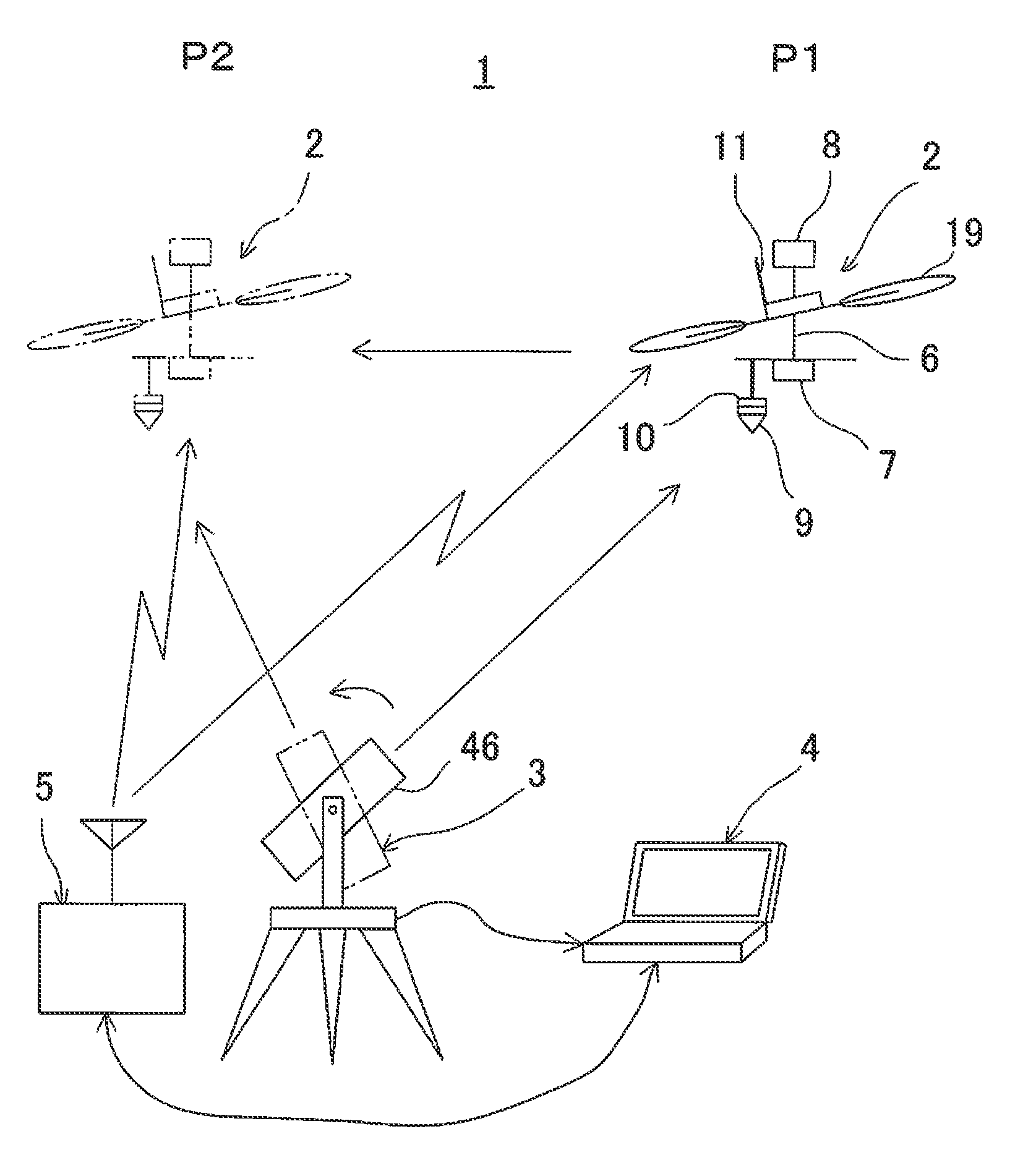
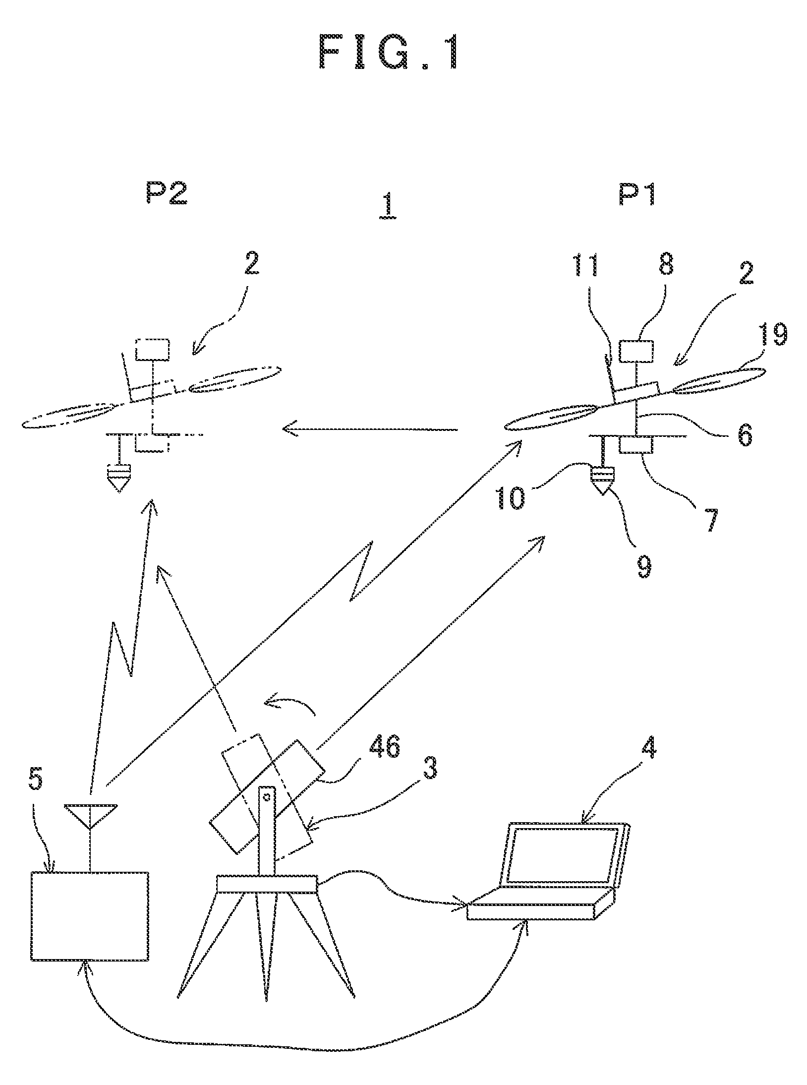
[0027]A measuring system 1 primarily comprises one each of a flying vehicle system (UAV) 2, a position measuring device 3, a ground base station 4 and a remote controller 5. FIG. 1 shows a case where a total station (TS) is used as the position measuring device 3.

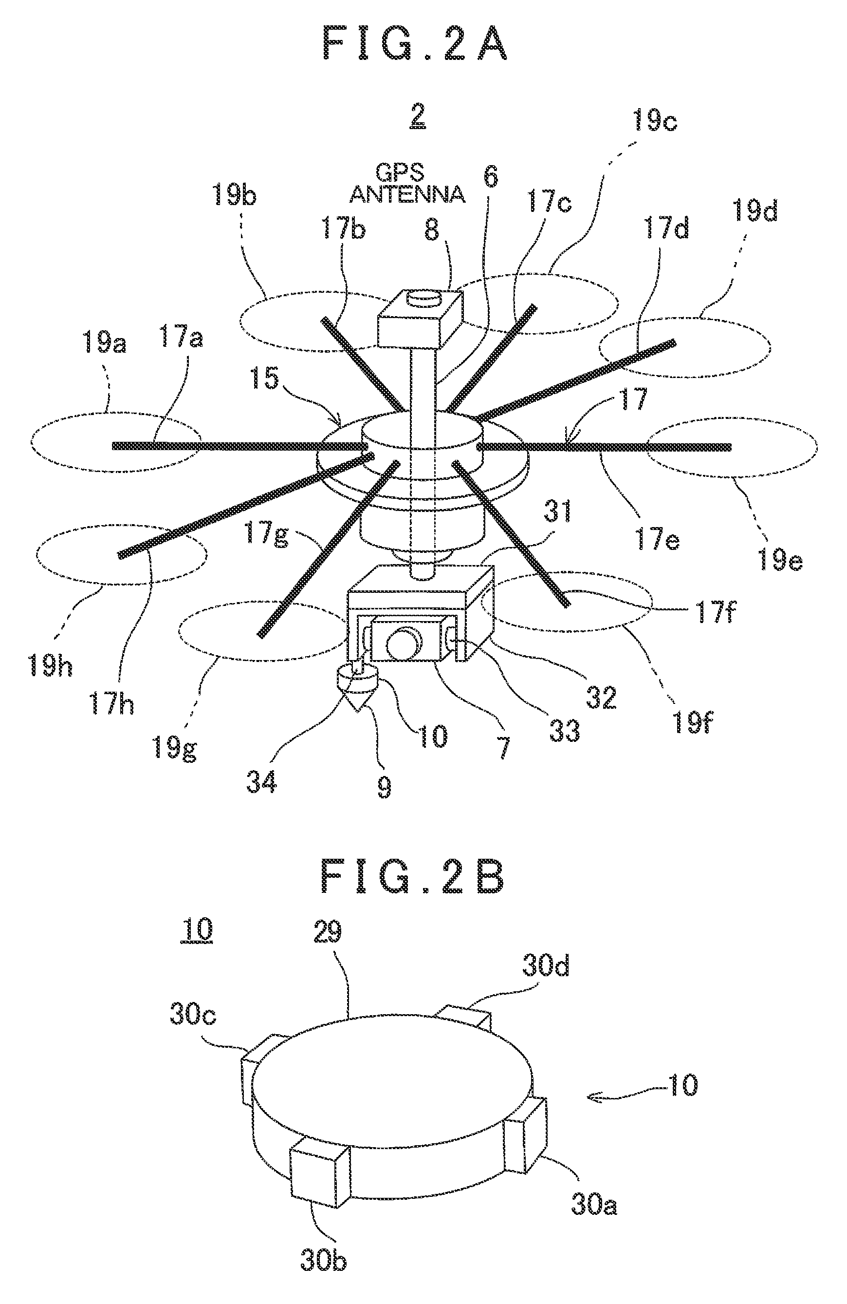
[0028]The flying vehicle system 2 primarily comprises a flying vehicle 15 (to be described later), a shaft 6 as a supporting member vertically supported on the flying vehicle 15 via a gimbal mechanism, a camera 7 disposed at a lower end of the shaft 6 and used as a photographing device, a GPS device 8 disposed at an upper end of the shaft 6, a prism 9 as a retro-reflector and disposed at a lower end of the shaft 6, a direction angle sensor 10 integrally mounted with the prism 9 and disposed...


PUM


Abstract

The invention provides a measuring system comprising a remotely controllable flying vehicle system with a GPS device and a measuring device installed thereon, a position measuring device installed at an arbitrary position and able to measure distance and angle and to track, a ground base station for controlling a flight of a flying vehicle, a remote controller able to give and take data to and from the ground base station and able to perform wireless communication to and from the flying vehicle system, and a control unit provided on the flying vehicle system or the ground base station, wherein the flying vehicle system has a retro-reflector as an object to be measured and the position measuring device is constructed so as to track the retro-reflector and perform distance measurement and angle measurement, wherein the flying vehicle system obtains GPS coordinates by the GPS device at least at two points during flight, the position measuring device measures positions of the two points of the flying vehicle system from an installation point, wherein the position measuring device measures positions of the flying vehicle system at the two points from the installation points, and either one of the control units are configured so as to obtain an absolute coordinate or GPS coordinate of the installation point of the position measuring device based on the GPS coordinates of the two points and based on distance measurement results and on angle measurement results by the position measuring device.

Description

BACKGROUND OF THE INVENTION[0001]The present invention relates to a measuring system, which performs measurement on a structure or the like using an unmanned aerial vehicle (UAV).[0002]In recent years, with the progress of UAV (Unmanned Aerial Vehicle), various types of apparatuses are installed on the UAV and operations as required are carried out by remotely controlling the UAV or by automatically flying the UAV. For instance, a camera for photogrammetry and a scanner are installed on the UAV, and measurement from up in the sky toward a position at lower level is performed or measurement is performed at a place where no operator can enter. Further, for the positional measurement of the UAV itself, a GPS device is installed on the UAV, and a position of the UAV is measured by using the GPS device.[0003]However, at a side of a dam or a building or at a place under a bridge, radio waves from artificial satellites cannot be received and positional measurement of the UAV cannot be perf...

Claims


Application Information

Patent Timeline
Patent Type & Authority Patents(United States)
IPC IPC(8): G05D1/00G05D3/00G06F7/00G06F17/00G01S19/13
CPCG01S19/13G05D1/0011G01C11/00G01C15/002G01S19/42G05D1/0094G08G5/0069G08G5/0073
Inventor OHTOMO, FUMIOKUMAGAI, KAORUOSARAGI, KAZUKIOTANI, HITOSHI
Owner KK TOPCON
Why Eureka
Try Eureka