Composite material FADEC box support

a technology of composite materials and box supports, which is applied in the direction of instruments, jet propulsion plants, electrical apparatus construction details, etc., can solve the problems of large deformation of casings, large impact on weight and extra cost, and severe installation constraints, so as to achieve the effect of reducing the drawbacks

Active Publication Date: 2015-12-01
SAFRAN
View PDF33 Cites 6 Cited by
  • Summary
  • Abstract
  • Description
  • Claims
  • Application Information

AI Technical Summary

Benefits of technology

[0005]An object of the present invention is to mitigate those drawbacks by proposing to place the computer in a box that forms its own support and that can be connected directly to the casing of the engine. The invention thus seeks to provide a solution to the problem posed by the connection between the computer and the casing that is simple, inexpensive, and effective.
[0007]Thus, by eliminating the supports, with their function now being provided by the tabs of the box, the number of components in the structure surrounding the computer is limited, and by making that box out of a composite material, its weight is considerably reduced.
[0010]In order to satisfy the requirements associated with electrical conductivity and removing heat by radiation, said box is preferably made of a composite material that conducts heat, and depending on the looked-for level of protection, it may also be covered in a layer of metal so as to satisfy the requirements associated with protection against electromagnetic radiation, it also being possible for said layer of metal of said box to be covered in an intumescent paint in order to reinforce protection against fire.

Problems solved by technology

Specifically, installing the FADEC in a non-fire zone (i.e. a zone in which it is not possible for flammable liquids to meet a source of ignition) that is spaced apart from the engine compartment by firewalls, or indeed installing the FADEC in the fuselage of the airplane, would lead to severe constraints in terms of installation, and to impacts on weight and to extra cost as a result of the additional connections and difficulties of maintenance.
If there is an impact of a blade against the casing, the casing may be subjected to a large amount of deformation.
Firstly the resulting structure is particularly heavy, which is most unwelcome in the field of aviation in which any reduction in on-board weight is welcome, and secondly that structure requires a large number of distinct components in order to be implemented, thereby involving industrial management that is burdensome and expensive.

Method used


Image

  • Composite material FADEC box support
  • Composite material FADEC box support

Examples


Embodiment Construction

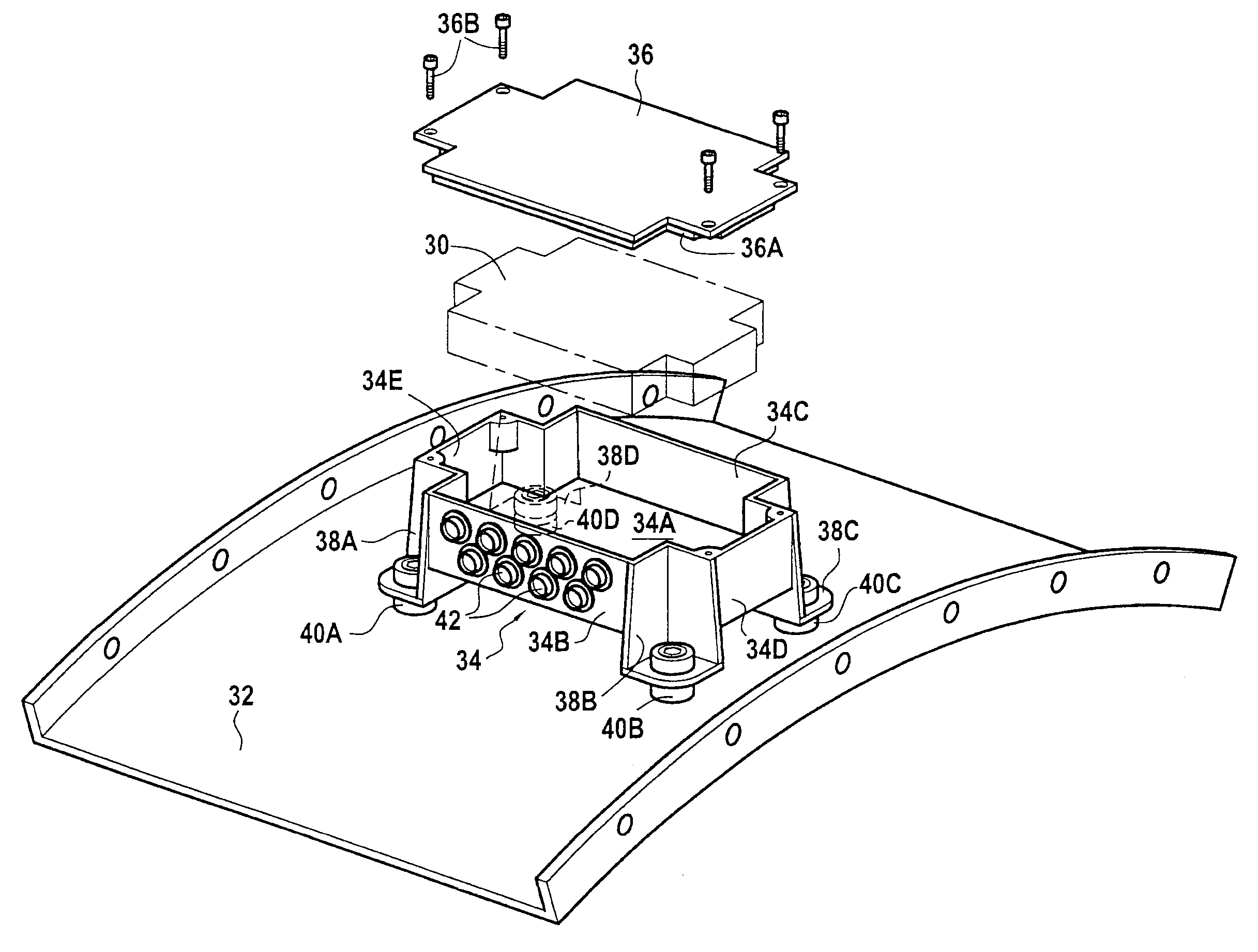
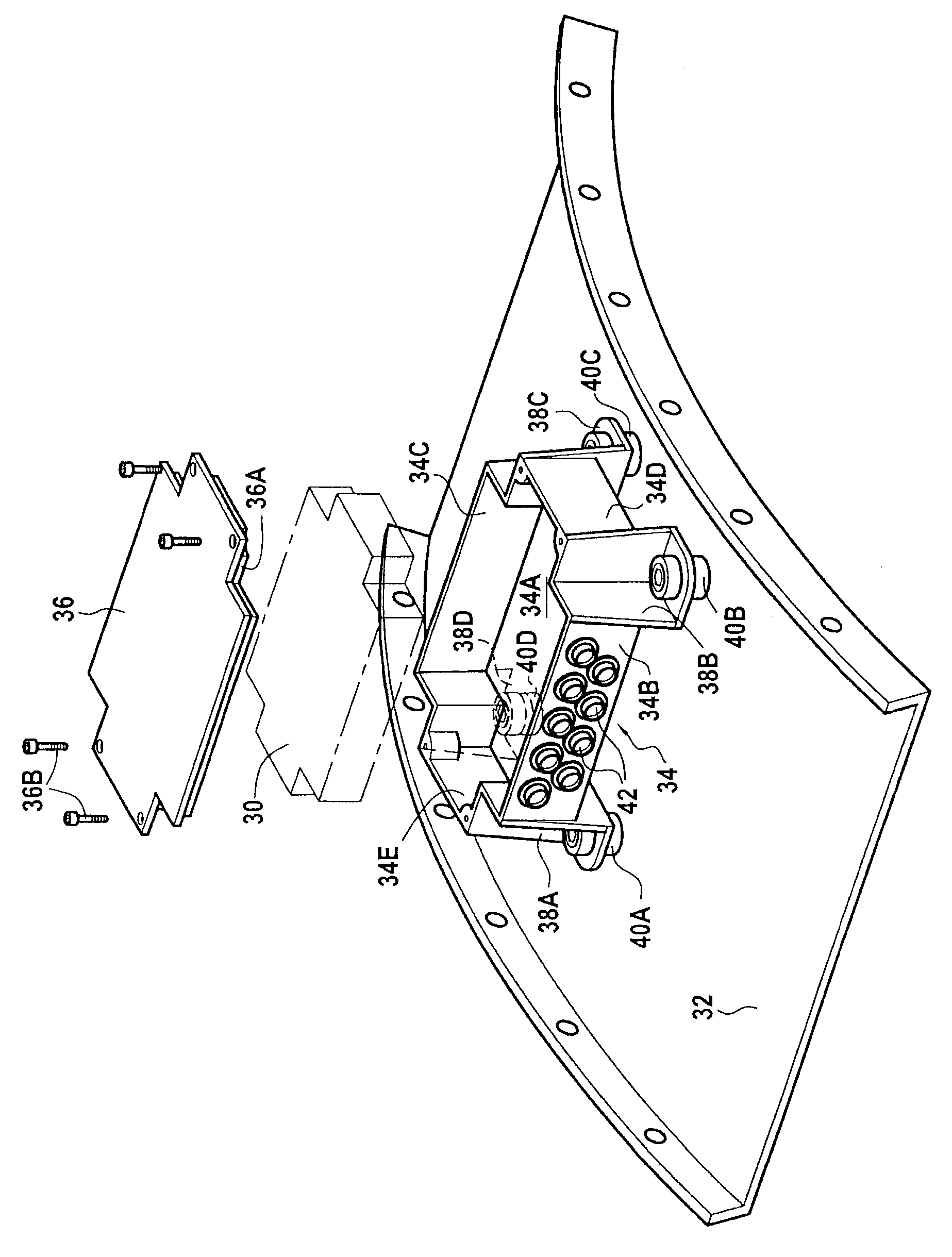
[0014]The way the FADEC 30 is fastened on a portion of the casing 32 of an aircraft turbine engine in accordance with the invention is shown in the sole FIGURE, which shows a device for protecting a computer, which device comprises a box 34 for containing the computer 30 and a cover 36 covering the box. The box is supported by tabs 38A-38D forming integral portions of the box and secured via resilient studs 40A-40D to the engine casing. The tabs serve to maintain a flow of air between the bottom 34A of the box and the portion of the engine casing on which it is secured. The studs are typically made of elastomer, they isolate the computer 30 from engine vibration, and they are directly in contact with the casing of the turbine engine.

[0015]In the example shown, the box 34 is substantially in the form of a rectangular parallelepiped and, in addition to the bottom 34A, it includes two longitudinal side walls 34B, 34C, and two side walls 34D, 34E defining four corners from which the tab...


PUM


Abstract

A device for protecting a computer of an aircraft turbine engine, the device comprising a box containing the computer and a cover covering the box, the box being supported by tabs forming integral portions of the box and maintaining a flow of air between the bottom of the box and a portion of the casing of the engine on which they are to come into secure contact via resilient studs, the box being made of a composite material.

Description

BACKGROUND OF THE INVENTION[0001]The present invention relates to the general field of aviation turbine engines, and in particular turbojets. More particularly, it relates to a device for protecting the full authority digital engine control (FADEC) and that is capable under all circumstances of ensuring that the FADEC is maintained on a portion of the casing of the engine.[0002]In most aeroengines presently in service, the FADEC is fastened to the fan casing, and thus in a zone that is particularly sensitive to fire. Specifically, installing the FADEC in a non-fire zone (i.e. a zone in which it is not possible for flammable liquids to meet a source of ignition) that is spaced apart from the engine compartment by firewalls, or indeed installing the FADEC in the fuselage of the airplane, would lead to severe constraints in terms of installation, and to impacts on weight and to extra cost as a result of the additional connections and difficulties of maintenance.[0003]The FADEC is conve...

Claims


Application Information

Patent Timeline
Patent Type & Authority Patents(United States)
IPC IPC(8): H05K7/20H05K5/03H05K5/00H05K5/02G06K1/20H01L23/473
CPCH05K5/03G06K1/20H05K7/20127H05K5/0213H05K5/0234H05K5/0073H05K5/0204H05K7/20145F01D25/24F02C7/20F02C7/32G06F1/20
Inventor BALK, WOUTERMANDEL, ROBIN
Owner SAFRAN
Why Eureka
Try Eureka