Gasification system

a gasification system and gasification method technology, applied in the field of gasification methods and equipment, can solve the problems of difficult or impossible to achieve, impracticality, etc., and achieve the effect of reducing the relative abundance of solid materials, maximizing the effectiveness of directing gas away from the second region, and minimizing energy consumption in the second region

Active Publication Date: 2015-12-08
INENTEC
View PDF49 Cites 3 Cited by
  • Summary
  • Abstract
  • Description
  • Claims
  • Application Information

AI Technical Summary

Benefits of technology

[0012]As used herein a “gas solid separator” includes any device or method that separates, in whole or in part, any portion of a solid particulate material entrained in a gas stream from that gas stream. While it may be desirable to remove all of the solid particulate material from the effluent gas, it may be impractical, difficult or impossible to do so. Accordingly, it is not necessary that the gas solid separator of the present invention remove all of the solid particulate material. Rather, to achieve the advantages of this aspect of the present invention, the gas solid separator must simply separate at least some of the solid material, and thereby decrease the relative abundance of these solid materials in the effluent gas. As used herein a “gas solid separator” includes any device or method that is capable of providing this separation. While not meant to be limiting, it is preferred that the gas solid separator allow at least 50% of the gas from the first region to be directed away from the second region through at least one primary gas duct. The effectiveness of directing the gas away from the second region can be maximized by placing the primary gas duct proximate to the means of controlling flow from the first region to the second region.
[0013]The gasification system of the present invention further includes a second region heated by an electrical means and a means for controlling the rate of flow of the material from the first region into the second region. By providing the gas solid separator, the synthesis gas produced in the first region is cleaned and diverted away from the second region. In this manner, the energy consumption in the second region is minimized while still producing a clean synthesis gas.

Problems solved by technology

While it may be desirable to remove all of the solid particulate material from the effluent gas, it may be impractical, difficult or impossible to do so.

Method used


Image

  • Gasification system
  • Gasification system
  • Gasification system

Examples


Embodiment Construction

[0035]For the purposes of promoting an understanding of the principles of the invention, reference will now be made to the embodiments illustrated in the drawings and specific language will be used to describe the same. It will nevertheless be understood that no limitations of the inventive scope is thereby intended, as the scope of this invention should be evaluated with reference to the claims appended hereto. Alterations and further modifications in the illustrated devices, and such further applications of the principles of the invention as illustrated herein are contemplated as would normally occur to one skilled in the art to which the invention relates.

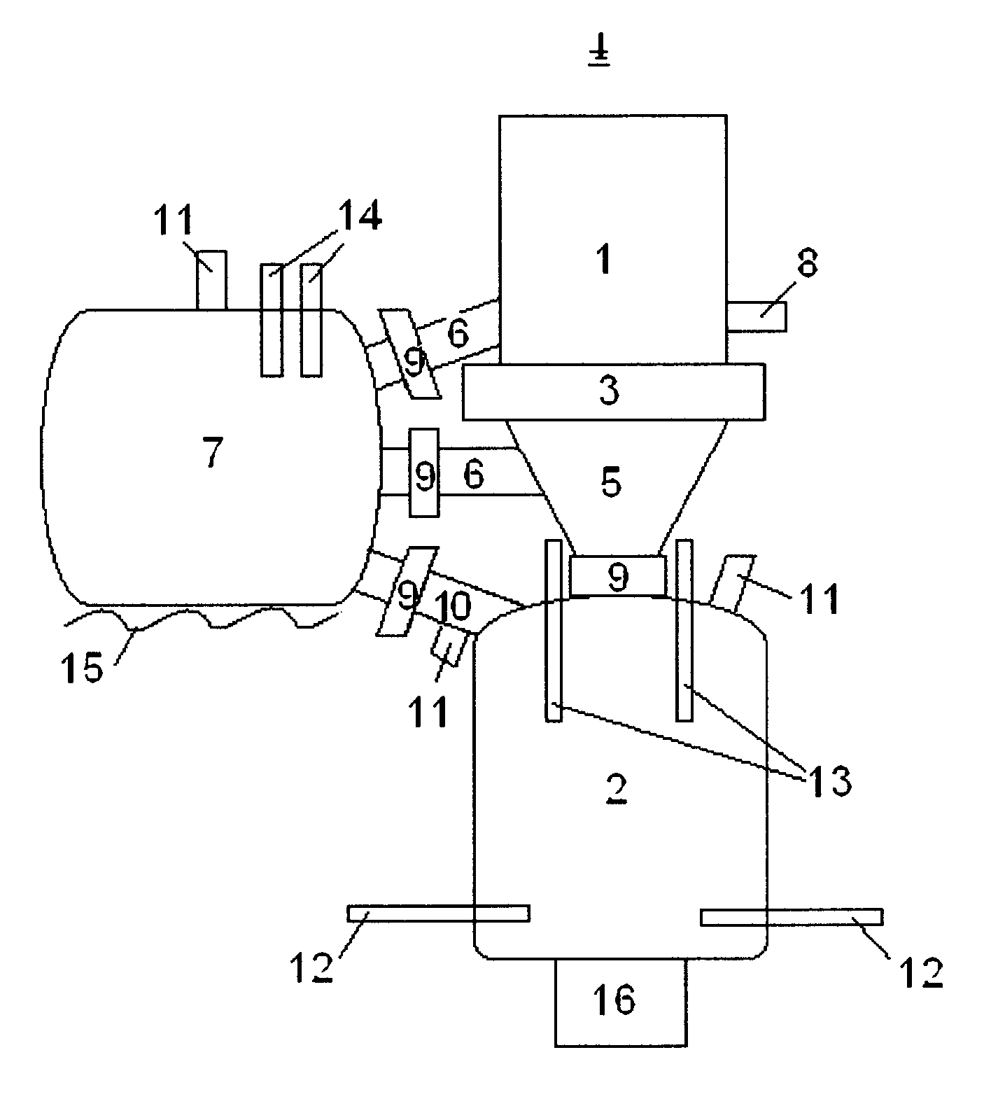
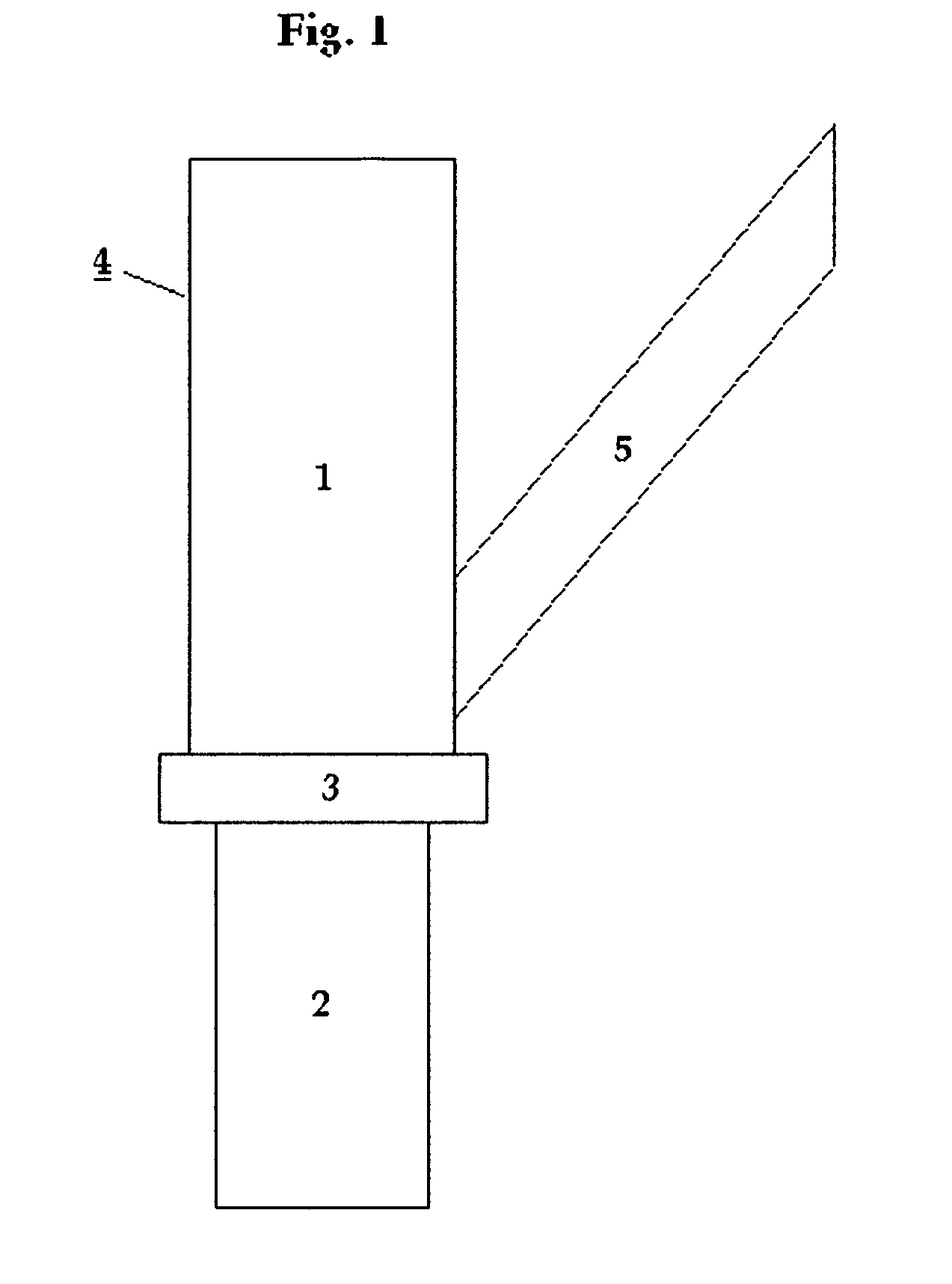
[0036]FIG. 1 is an illustration of the gasification system 4 of the present invention showing a simple form of the gas solid separator 5 used in the present invention. While this example of the gas solid separator 5 is not necessarily the preferred embodiment of this aspect of the present invention, it is useful to illustrate th...


PUM

PropertyMeasurementUnit
temperatureaaaaaaaaaa
residence timeaaaaaaaaaa
gas residence timeaaaaaaaaaa

Abstract

A gasification system method and apparatus to convert a feed stream containing at least some organic material into synthesis gas having a first region, a second region, a gas solid separator, and a means for controlling the flow of material from the first region to the second region. The feed stream is introduced into the system, and the feed stream is partially oxidized in the first region thereby creating a solid material and a gas material. The method further includes the steps of separating at least a portion of the solid material from the gas material with the gas solid separator, controlling the flow of the solid material into the second region from the first region, and heating the solid material in the second region with an electrical means.

Description

CROSS REFERENCE TO RELATED APPLICATIONS[0001]This application is a continuation of U.S. application Ser. No. 12 / 154,579 filed May 23, 2008, now U.S. Pat. No. 8,118,892 which is a continuation-in-part of U.S. application Ser. No. 11 / 432,826 filed May 12, 2006 for COMBINED GASIFICATION AND VITRIFICATION SYSTEM, now U.S. Pat. No. 7,854,775 and U.S. application Ser. No. 12 / 008,956 filed Jan. 14, 2008 for GRATE FOR HIGH TEMPERATURE GASIFICATION SYSTEMS, now U.S. Pat. No. 8,118,891.TECHNICAL FIELD[0002]This invention relates to methods and apparatus for gasifying materials. More specifically, this invention related to methods and apparatus for economically producing energy and responsibly disposing of waste material by gasifying and vitrifying waste material.BACKGROUND OF THE INVENTION[0003]There have been numerous examples of methods and apparatus for generating synthesis gas from waste materials. There have also been numerous examples of methods and apparatus for generating synthesis ga...

Claims


Application Information

Patent Timeline
Patent Type & Authority Patents(United States)
IPC IPC(8): C10J3/26C10J3/74C10J3/34C10J3/84C10J3/40C03B5/00C03B5/02C03B5/027C10J3/08
CPCC10J3/26C03B5/005C03B5/025C03B5/027C10J3/08C10J3/40C10J3/74C10J3/84C10J2200/12C10J2200/152C10J2300/0946C10J2300/0956C10J2300/0976C10J2300/1238C10J2300/1276C10J2300/16C10J2300/1634C10J3/721C10J2200/15C10J2200/158C10J2300/1846Y02P20/145
Inventor SURMA, JEFFREY E.BATDORF, JAMES A.
Owner INENTEC
Why Eureka
Try Eureka