Oil field test and separation system

a separation system and oil field technology, applied in separation processes, liquid degasification, chemistry apparatus and processes, etc., can solve the problems of inaccurate metering when, the current device and method does not satisfactorily address all the prior problems, and the cost of testing and measuring equipment, etc., to achieve accurate fluid measurement

Active Publication Date: 2015-12-22
CALDWELL DENNIS P
View PDF3 Cites 6 Cited by
  • Summary
  • Abstract
  • Description
  • Claims
  • Application Information

AI Technical Summary

Benefits of technology

[0003]The invention relates to a system for separating and measuring mixed fluids. Specifically the invention may be applied to the separation of crude oil, gas, and water coming from a production well and the volumetric measurement of crude oil and water using a mechanical portable device. More particularly, the invention relates to a system involving a fluid control manifold, a gas vent affixed to the top of a surge tank whereby the gas may be removed from the fluid mixture before entering the fluid separator, a spill preventer inhibiting an oil spill in case of a gas vent failure, a separation apparatus with a separation vessel, an adjustable float within the vessel, which allows

Problems solved by technology

Problems encountered in the oil fields of the past have been identified as: (1) the accuracy of the measurement of the volume of constituent fluids being extracted from the well and transferred to the tank batteries; (2) the cost of the testing and measuring equipment; (3) the portability of the testing and measuring equipment; (4) fluid spills; and (5) diagnostic testing of the metering equipment in the field
Current devices and methods do not satisfactorily address all these prior problems.
However one serious drawback involved incorrect metering when and if medium to high

Method used


Image

  • Oil field test and separation system
  • Oil field test and separation system
  • Oil field test and separation system

Examples


Embodiment Construction

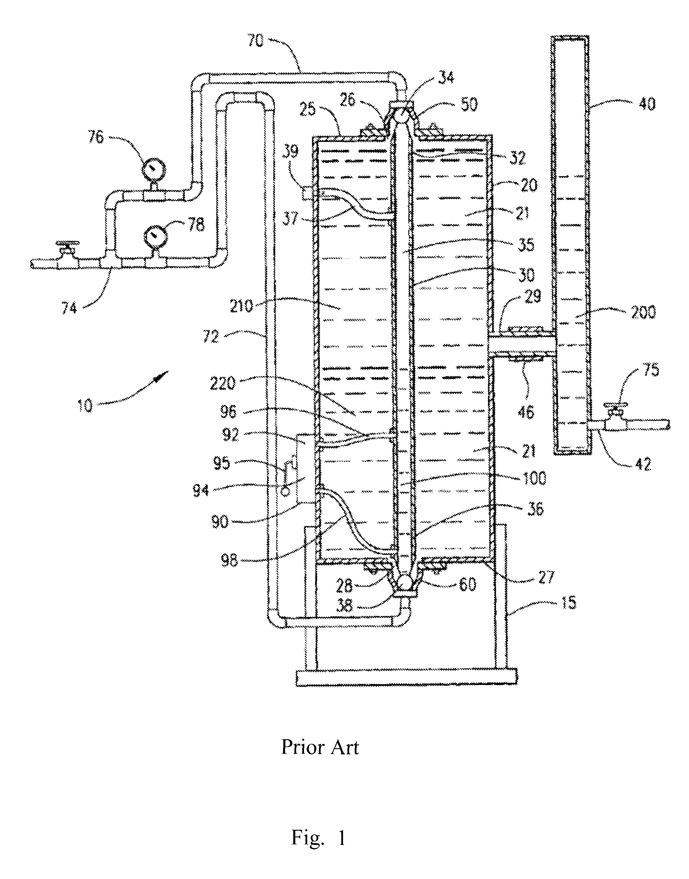
[0025]FIG. 1 shows the system of prior art U.S. Pat. No. 6,736,964 herein incorporated by reference an apparatus for separating and measuring mixed fluids, directed especially towards the separation of crude oil and water and the volumetric measurement of each of the primary constituent fluids, the apparatus 10 comprising essentially a vertically oriented cylindrical vessel 20 positioned on a support frame 15, the vessel 20 having an interior 21, an exterior surface, an upper outlet 26 located in a top portion 25 of the vessel 20, a lower outlet 28 located in a bottom portion 27 of the vessel 20 and an inlet 29 located approximately half way between the top portion 25 and bottom portion 27 from the exterior surface into the interior 21 of the vessel 20, an adjustably buoyant vertical float member 30 positioned within the interior 21 of the vessel 20, the float member 30 having an upper end 32 and a lower end 36, an upper housing 50 attached to the upper outlet 26, a lower housing 60...


PUM

PropertyMeasurementUnit
Volumeaaaaaaaaaa

Abstract

An improved fluid separator and tester having a vessel, an adjustably buoyant float member, an external surge tank, and a gas vent connected to the fluid separator having a float and gas valve assembly, the improvement comprising a set of risers set to equal height, at least one valve to redirect fluid flow to test flow meters, and a spill preventer having a connection to a vertical gas valve, a housing, at least one internal freely movable float, upper float seat adapted to receive a float to seal and prevent the escape of particulates while allowing the venting of gas, a float support means, and discharge means for expelling the contents, whereby the improvements provide increased accuracy in determining a volume of each type of input fluid during operations, allow for the assessment of proper operation of the meters, and prevent environmental contamination in the event of system malfunction.

Description

CROSS-REFERENCE TO RELATED APPLICATIONS[0001]None.FIELD OF THE INVENTION[0002]The invention generally relates to separation of a fluid mixture into its components of oil, gas, and water and meter the volumes of the oil and water components produced.SUMMARY OF THE INVENTION[0003]The invention relates to a system for separating and measuring mixed fluids. Specifically the invention may be applied to the separation of crude oil, gas, and water coming from a production well and the volumetric measurement of crude oil and water using a mechanical portable device. More particularly, the invention relates to a system involving a fluid control manifold, a gas vent affixed to the top of a surge tank whereby the gas may be removed from the fluid mixture before entering the fluid separator, a spill preventer inhibiting an oil spill in case of a gas vent failure, a separation apparatus with a separation vessel, an adjustable float within the vessel, which allows the fluid of lower specific grav...

Claims


Application Information

Patent Timeline
IPC IPC(8): B01D19/00B01D17/02B01D17/12
CPCB01D17/02B01D19/0063B01D19/0068B01D17/12B01D17/0208
Inventor CALDWELL, DENNIS P.
Owner CALDWELL DENNIS P
Why Eureka
Try Eureka