Burner and method for operating a burner

a burner and burner technology, applied in the direction of engine starters, engine/propulsion engine ignition, lighting and heating apparatus, etc., can solve the problems of economic unattractive operation with natural gas, reduce the maximum efficiency of the overall system, etc., and achieve the effect of improving the swirling of oxidation means and reducing volum

Inactive Publication Date: 2015-12-22
SIEMENS AG
View PDF43 Cites 23 Cited by
  • Summary
  • Abstract
  • Description
  • Claims
  • Application Information

AI Technical Summary

Benefits of technology

[0014]The invention further makes it possible for the syngas operation to largely correspond to diffusion operation, while natural gas operation largely corresponds to a premixing principle. This makes operation of a syngas burner operation with natural gas economically attractive for example.
[0016]Preferably the separation means is made of metal or a metal alloy, especially a sheet metal. This is especially simple and low-cost to realize and in addition has the necessary resistance to high temperatures.
[0018]Preferably at least one fuel nozzle is provided and the fuel, especially natural gas, can be injected through the at least one fuel nozzle into an oxidation means mass flow, especially air swirled by the swirl generator, especially air swirl generator, in the mixing zone. Preferably in this case the at least one fuel nozzle is arranged in one or more rows lying behind one another downstream of the swirl generator, especially the air swirl generator. In this case the swirl generator can have swirl blades for improved swirling of the oxidation means, especially the air. An arrangement of the at least one fuel nozzle on these swirler blades is especially advantageous since a good mixing of the injected fuel with the oxidation means is produced.

Problems solved by technology

The use of steam / nitrogen as a thinning means in syngas combustion reduces the maximum level of efficiency of the overall system.All previous syngas burners require the addition or mixing-in of an inerting medium (steam) to reduce the peak temperatures and thereby the NOx emissions.
Because of the underlying design of the syngas burner with syngas as primary fuel however very large quantities of inerting medium would be necessary, making operating with natural gas economically unattractive, e.g. if the concept of diffusion combustion with addition of an inerting medium is also used in natural gas operation.

Method used


Image

  • Burner and method for operating a burner
  • Burner and method for operating a burner

Examples


Embodiment Construction

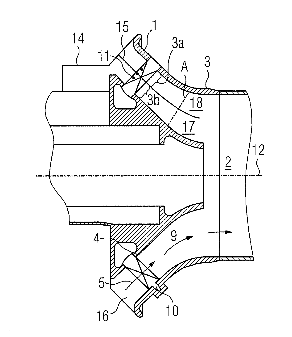
[0027]The invention will be explained below in greater detail with reference to FIG. 1. FIG. 1 shows a schematic diagram of a section through a part of a burner with a channel 1. The channel 1 includes a mixing zone 2, a swirl generator 10, here embodied as an air swirl generator 10, and one or more fuel nozzles 11. The mixing zone 2 is arranged radial-symmetrically around the central axis 12. The outer side of the zone 2 seen from the central axis 12 is referred to below as the cone side 3. The side of the premixing zone 2 facing towards the central axis 12 is referred to below as the hub side 4.

[0028]An oxidation means mass flow, especially an air mass flow 5, reaches the air swirl generator 10 via a supply, especially air supply 16; the direction of flow of the supplied air mass flow is indicated by arrows 5. This flow can also involve an air / fuel mixture already enriched. The air swirl generator 10 swirls the air mass flow 5 and forwards this into the zone 2. From there the air ...


PUM


Abstract

A burner and a method for operating a burner are provided. The burner includes a channel having a mixing zone and having a feed for an oxidation means, particularly an air feed, and at least one fuel feed for injecting fuel, wherein a separating means which divides the channel over a wide range of the channel into at least two separated channels, namely a first channel and a second channel, is provided in the channel. The method for operating a burner having a channel includes a mixing zone into which an oxidation mass flow and fuel are injected, wherein two substantially separate flow paths are formed by means of a separating means in the channel and the at least two separated first and second channels, formed by the separating means.

Description

CROSS REFERENCE TO RELATED APPLICATIONS[0001]This application is the US National Stage of International Application No. PCT / EP2009 / 061846, filed Sep. 14, 2009 and claims the benefit thereof. The International Application claims the benefits of European Patent Office application No. 08017321.4 EP filed Oct. 1, 2008. All of the applications are incorporated by reference herein in their entirety.FIELD OF INVENTION[0002]The invention relates to a burner comprising a channel with a mixing zone and with an oxidation means supply, especially air supply, and at least one fuel supply for injection of fuel. The invention also relates to a method for operating such a burner.BACKGROUND OF INVENTION[0003]Dry natural gas premixing combustion is used for low-pollutant natural gas combustion. Premixing burners typically comprise a premixing zone in which air and fuel are mixed before the mixture is directed into a combustion chamber. The mixture burns in said chamber, with a hot gas being generated...

Claims


Application Information

Patent Timeline
Patent Type & Authority Patents(United States)
IPC IPC(8): F02C3/20F23R3/14F23R3/26F23R3/36
CPCF23R3/14F23R3/36F23R3/26F23R2900/00002
Inventor PRADE, BERND
Owner SIEMENS AG
Why Eureka
Try Eureka