
Modular lighting system

a module and lighting technology, applied in the field of module lighting systems, can solve the problems of increasing the cost of spare leds and lighting systems, reducing the light output of conventional lighting systems, and increasing the cost of spare leds and their control systems, and achieving cost-effective effects

Active Publication Date: 2015-12-29
SIGNIFY HLDG BV
View PDF20 Cites 5 Cited by
  • Summary
  • Abstract
  • Description
  • Claims
  • Application Information

AI Technical Summary

Benefits of technology

The system provides a cost-effective, scalable, and flexible lighting solution that maintains desired illumination levels by allowing for easy addition of modules and power adjustments, reducing the need for spare LEDs and complexity, thus lowering ownership costs and maintaining performance over time.

Problems solved by technology

Furthermore, the conventional lighting system provided with the LEDs suffers from a decreasing light output during the lifetime due to ageing of the LEDs.
The spare LEDs makes the lighting system more expensive, in particular because the spare LEDs and their control systems are relatively expensive in comparison with to the projected price of LEDs at a point of time in the future when the spare LEDs in the lighting system will be actually used.
Moreover, these spare LEDs and associated controllers add complexity and weight to the lighting system.

Method used


Image

  • Modular lighting system
  • Modular lighting system
  • Modular lighting system

Examples


first embodiment

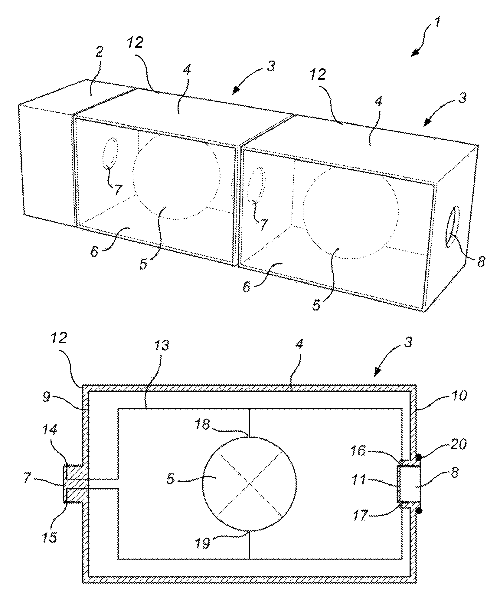
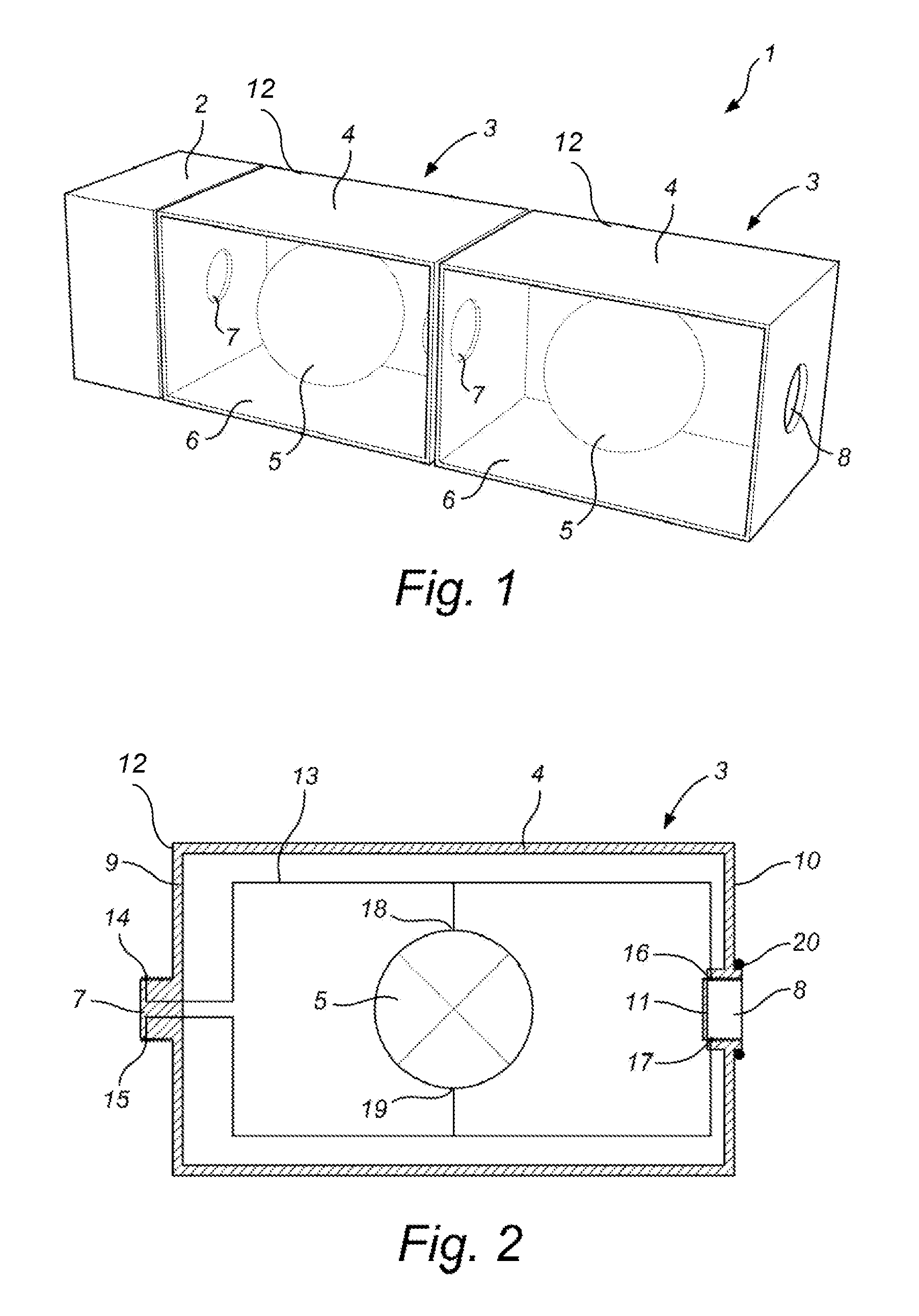
[0044]FIG. 2 shows a schematic view of a module 3 for use in this lighting system 1. The other module 3 of the lighting system can be similar to the described module 3. The module 3 comprises for example, a block shaped housing having a peripheral wall 4, which is closed at one and provided with the light exit window 6. The other end can be provided with a transparent bottom 6, the material of the bottom can be, for example, polymethylmeta-acrylate (PMMA) to obtain a waterproof and dustproof module. The peripheral wall 4 can have a rectangular cross-section. The top and the peripheral wall 4 can be made of a plastic material e.g. ABS or PVC.

[0045]The module 3 further comprises a first connector and a second connector. The first connector, for example, a screw 7 is provided in a first side 9 of the peripheral wall 4. The second connector, in this embodiment, a screw nut or threaded hole 8 is provided in a second side 10 of the peripheral wall 4 opposite the screw 7 in the first side...

second embodiment

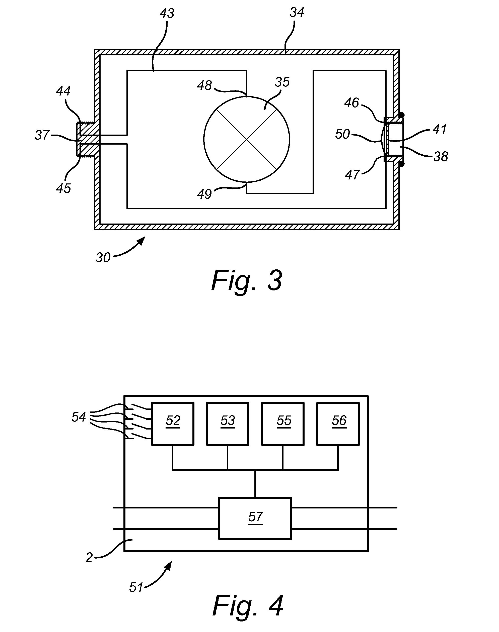
[0058]The controller 2 of the lighting system driving the modules 30 according to this second embodiment is of a constant current mode and is connected to a conventional mains or other power source. The electrical voltage of the power source, may be an AC mains voltage, e.g. 230V, 50 Hz, or a DC-Voltage from a DC-Grid, e.g. 400V. The controller 2 converts this voltage to a constant voltage for driving the LEDs 5.

[0059]FIG. 4 shows a schematic diagram of a controller 2 for use in the lighting system 1. The controller 2 may be provided with a processor 53 with a storage device 52 for storing a current electrical load of the lighting system, the storage can comprise, for example electrical switches 54, that can be used to select the electrical load of the lighting system 1. In combination or alternatively, some means of measuring the supply voltage and / or current required for any or all of the series or parallel connected modules can be used, which drive (e.g. by providing signals to t...


PUM


Abstract

The invention proposes a lighting system comprising a plurality of modules, the modifies respectively comprising: a housing provided with an exit window; at least one light source provided in the housing; wherein the lighting system further comprises: a controller arranged to drive light sources, an electrical circuit arranged to connect light sources with the controller, the electrical circuit further comprising a first pair of electrical contacts provided in a first module and a second pair of electrical contacts provided in a second module, the first and second pair of contacts being arranged for a mutual electrical connection.

Description

CROSS-REFERENCE TO RELATED APPLICATIONS[0001]This application is the U.S. National Phase application under 35 U.S.C. §371 of International Application No. PCT / IB2012 / 055184, filed on Sep. 28, 2012, which claims the benefit of U.S. Provisional Application No. 61 / 543,828, filed on Oct. 6, 2011. These applications are hereby incorporated by reference herein.FIELD OF THE INVENTION[0002]The invention relates to a lighting system and a module for a lighting system.BACKGROUND OF THE INVENTION[0003]A lighting system comprising modules which are respectively provided with light source, such as solid state-based light source, e.g. light emitting diodes (so-called LED), is known from the Chinese patent application CN201661928. That document discloses a lighting system comprising a frame, a controller and a number of modules. Each module comprises a LED. A number of modules are attached to the frame. In the lighting system the controller is connected to the LEDs for driving the LEDs.[0004]Light...

Claims


Application Information

Patent Timeline
Patent Type & Authority Patents(United States)
IPC IPC(8): F21V21/00F21V23/06F21S2/00F21V23/00F21V31/00F21V21/005F21V23/04F21Y101/02
CPCF21V23/003F21S2/005F21V23/06F21Y2101/02F21V23/008F21V23/04F21V31/005F21V21/005F21Y2115/10
Inventor RADERMACHER, HARALD JOSEPH GUNTHER
Owner SIGNIFY HLDG BV
Learn More