
Docking station

a technology for docking stations and docking tables, which is applied in the direction of electrical apparatus casings/cabinets/drawers, instruments, computing, etc., can solve the problems of limited application and operation, and achieve the effect of improving the operational stability of electronic devices and more space for operating electronic devices

Active Publication Date: 2015-12-29
PEGATRON
View PDF20 Cites 11 Cited by
  • Summary
  • Abstract
  • Description
  • Claims
  • Application Information

AI Technical Summary

Benefits of technology

[0008]An objective of the disclosure is to provide a docking station that can have more applications, enhance the operational stability of the electronic apparatus that is connected to the docking station, and provide more space for operating the electronic apparatus.
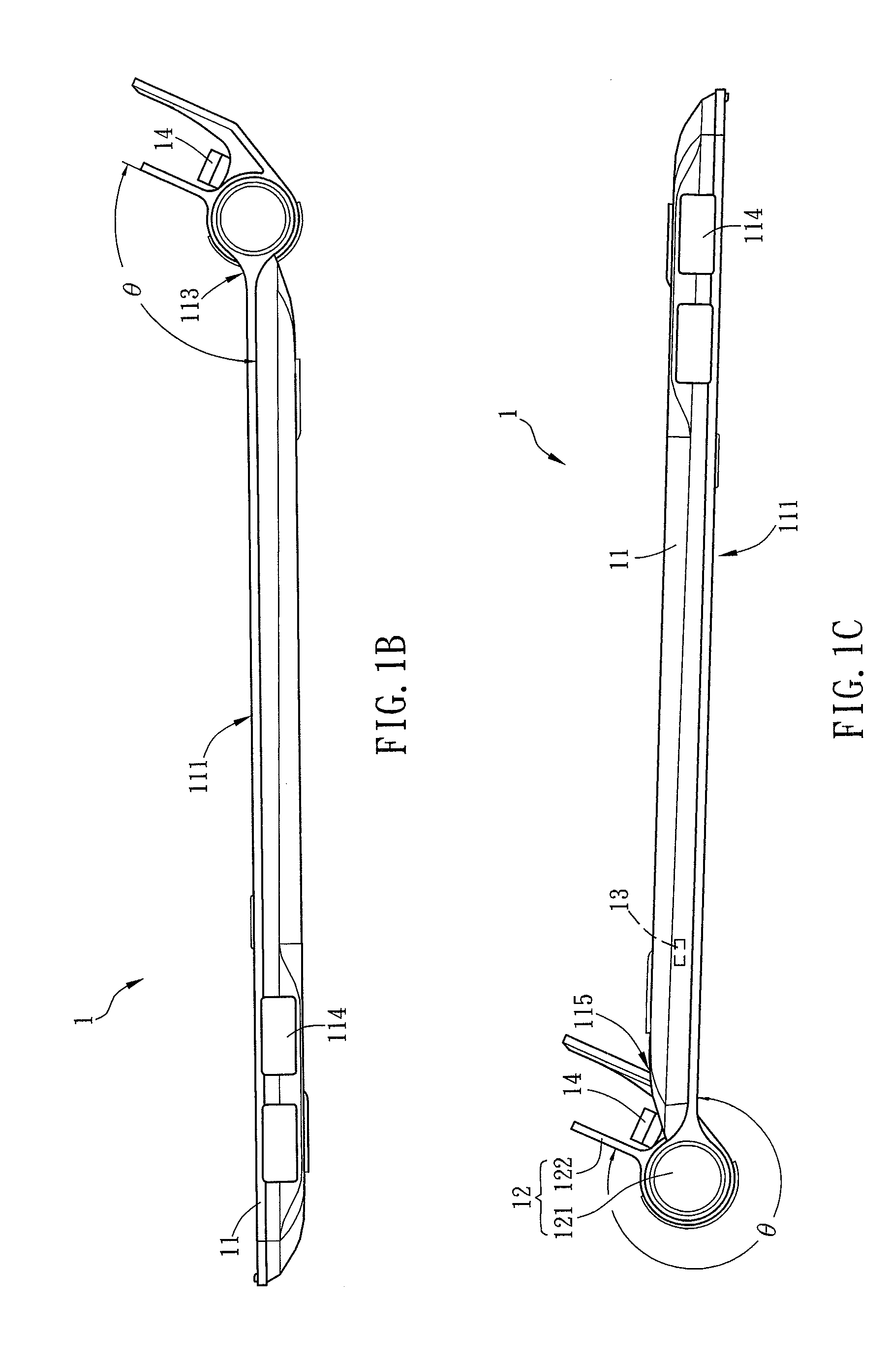
[0019]As mentioned above, the docking station of the disclosure includes a docking body and a hinge module, and a hinge element of the hinge module is connected to a hinge portion of the docking body and connected to a holding element of the hinge module. Besides, a groove is formed between the holding element and the docking body. Thereby, the holding element for holding an electronic apparatus can be rotated relative to the docking body for more than 270 degrees through the rotation space provided by the groove until being stopped by the docking body. Hence, the docking station of the disclosure can have more applications. When the electronic apparatus is disposed to the holding element of the docking station, the docking station can be regarded as the base of the electronic apparatus so as to improve the operational stability of the electronic apparatus. Furthermore, the more space for operating the electronic apparatus can be provided because the docking station is hidden behind.

Problems solved by technology

Although the conventional notebook is configured with a hinge structure, the largest rotation angle between the display and the main body is just about 180 degrees, so that the related application and operation are greatly limited.

Method used


Image

  • Docking station
  • Docking station
  • Docking station

Examples


Embodiment Construction

[0027]The present invention will be apparent from the following detailed description, which proceeds with reference to the accompanying drawings, wherein the same references relate to the same elements.

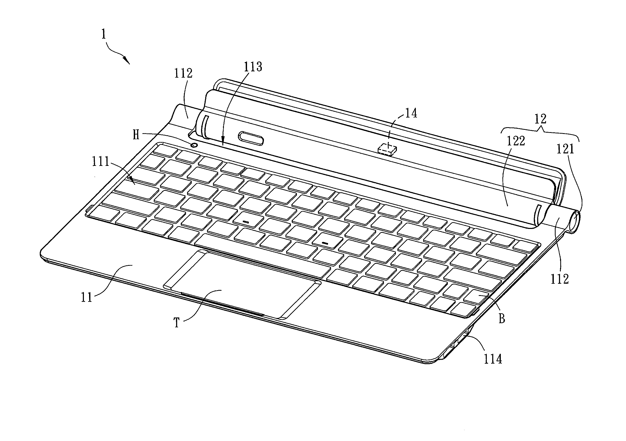
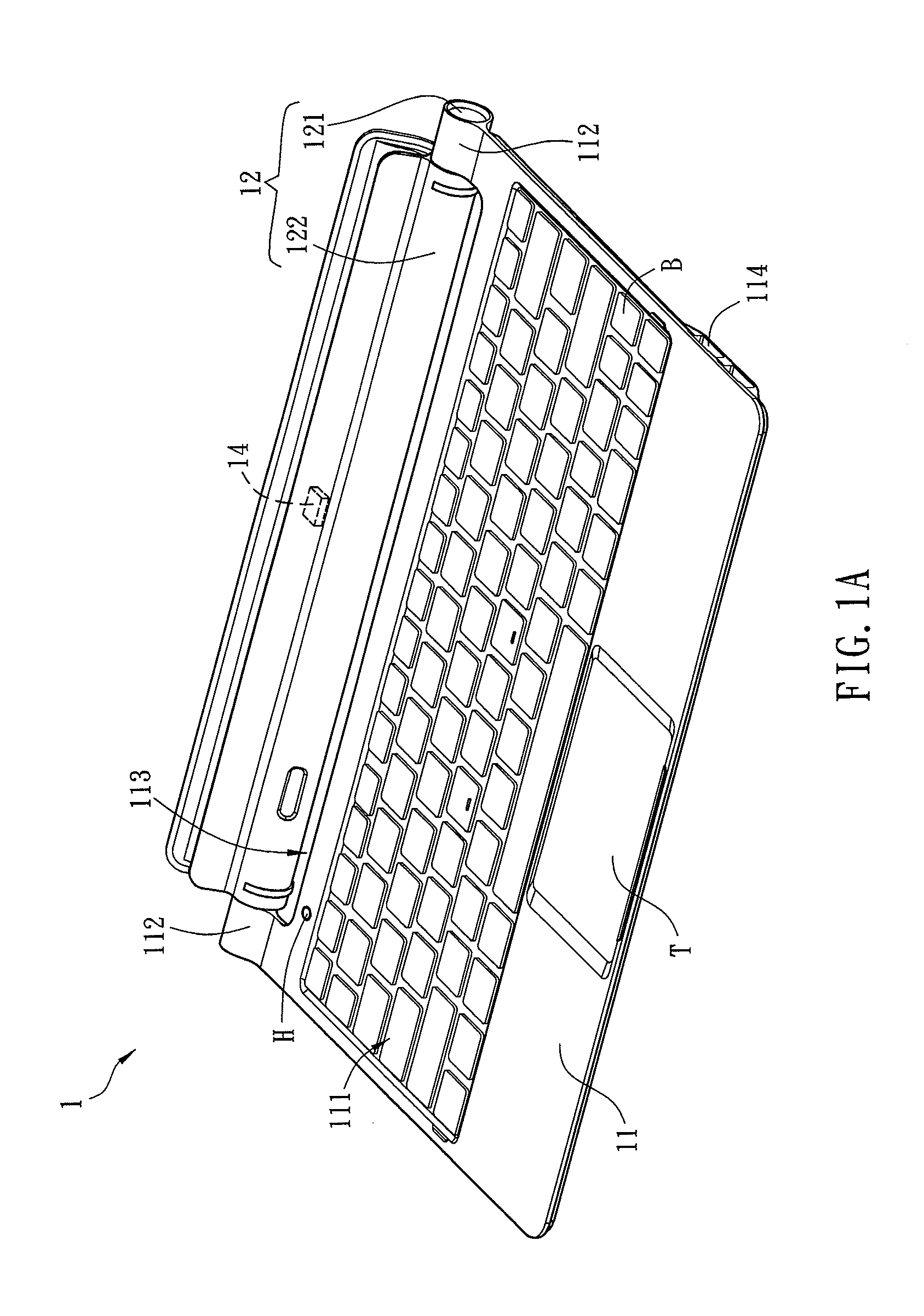
[0028]FIG. 1A is a schematic diagram of a docking station 1 of a preferred embodiment of the disclosure, and FIG. 1B is a side-view diagram of the docking station 1 as shown in FIG. 1A. The docking station 1 is used to hold an electronic apparatus.

[0029]Referring to FIGS. 1A and 1B, the docking station 1 includes a docking body 11 and a hinge module 12.

[0030]The docking body 11 includes an operation interface 111, which can include at least a key or at least a touch pad, or their combinations. The key can be a physical key or a virtual key. In this embodiment, the operation interface 111 has a plurality of keys B and a touch pad T, for example. The docking body 11 further includes a hinge portion 112. Herein, the hinge portion 112 is located at two sides of the docking body 11. Beside...


PUM


Abstract

A docking station is used to hold an electronic apparatus and includes a docking body and a hinge module. The docking body includes an operation interface and a hinge portion. The hinge module includes a hinge element and a holding element. The hinge element is pivotally connected to the hinge portion and connected to the holding element. The holding element and the docking body form a groove. The holding element for holding the electronic apparatus is rotatable relative to the docking body for more than 270 degrees through the rotation space provided by the groove until being stopped by the docking body.

Description

CROSS REFERENCE TO RELATED APPLICATIONS[0001]This Non-provisional application claims priority under 35 U.S.C. §119(a) on Patent Application No(s). 100148398 filed in Taiwan, Republic of China on Dec. 23, 2011, the entire contents of which are hereby incorporated by reference.BACKGROUND[0002]1. Technology Field[0003]The disclosure relates to a docking station and, in particular, to a docking station that cooperates with an electronic apparatus.[0004]2. Related Art[0005]With the improved electronic technology, various consumer electronic products (such as a notebook computer, a portable player, a portable game machine, a PDA, an electronic dictionary, or a cell phone) are developed towards the trend of the miniaturization so that the user can easily carry and use them anytime. Besides, for reducing the storage space, a hinge structure is often applied to the electronic apparatus so that the display panel can rotate relative to the host to achieve the fold.[0006]Take the notebook as an...

Claims


Application Information

Patent Timeline
Patent Type & Authority Patents(United States)
IPC IPC(8): G06F1/16
CPCG06F1/1632G06F1/1669G06F1/1654
Inventor WANG, CHI-HANYEH, CHUN-LIANGHUANG, HUA-YUWANG, MEI-HUI
Owner PEGATRON
Learn More