Variable pliability actuator

a pliability actuator and variable technology, applied in the direction of dynamo-electric machines, multiple dynamo-electric motor speed regulation, dynamo-motor starters, etc., can solve the problems of reducing production efficiency, reducing production efficiency, and consequently increasing production costs, so as to reduce production times and costs, the effect of easy connection and greater simplicity

Active Publication Date: 2016-01-05
UNIV DI PISA CENT INTERDIPARTIMENTALE DI RICERCA E PIAGGIO
View PDF18 Cites 1 Cited by
  • Summary
  • Abstract
  • Description
  • Claims
  • Application Information

AI Technical Summary

Benefits of technology

[0022]Another important aim of the invention is to make an actuator allowing the whole potential capacity typical of a robot to be fully exploited so as to achieve lower production times and costs.
[0023]It is a further aim of the invention to conceive an actuator that can be easily connected to the remainder of the structure constituting a robot and that allows manufacture of a robot with greater simplicity.
[0025]Therefore, it is also an aim of the invention to make a variable pliability actuator enabling robots of reduced costs to be manufactured which however are characterized by high performance.

Problems solved by technology

This value therefore is only a compromise between the above described requirements and does not represent an ideal solution.
In conclusion, the presently known actuators are the cause for slowing down in production and for the consequent increase in the production costs.
Said problems are also present in service robotics, when robots are used in the home field where there is an almost continuous interaction between robot and person.
Specifically, the problem concerning safety is particularly felt in making games and other devices used by children, where it is of fundamental importance to avoid dangers under any use condition.
Another important problem is represented by the complexity and high manufacturing costs typical of a robot.
This is the result of complex assembling operations combined with a great number of connections to be made.

Method used


Image

  • Variable pliability actuator
  • Variable pliability actuator
  • Variable pliability actuator

Examples


Embodiment Construction

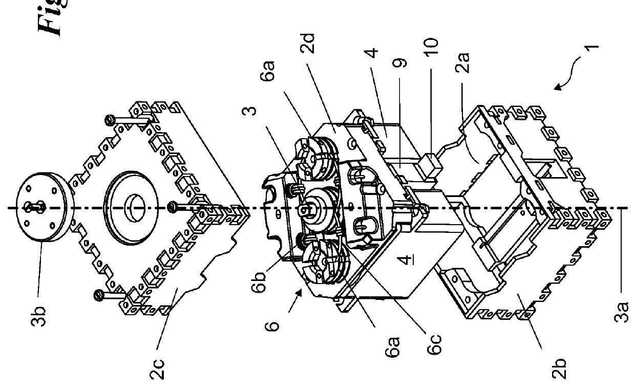
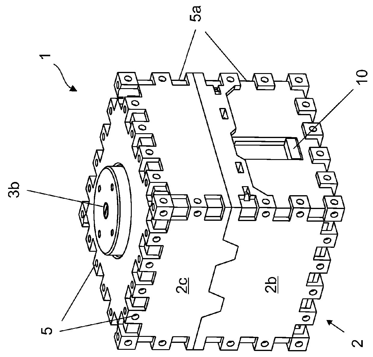
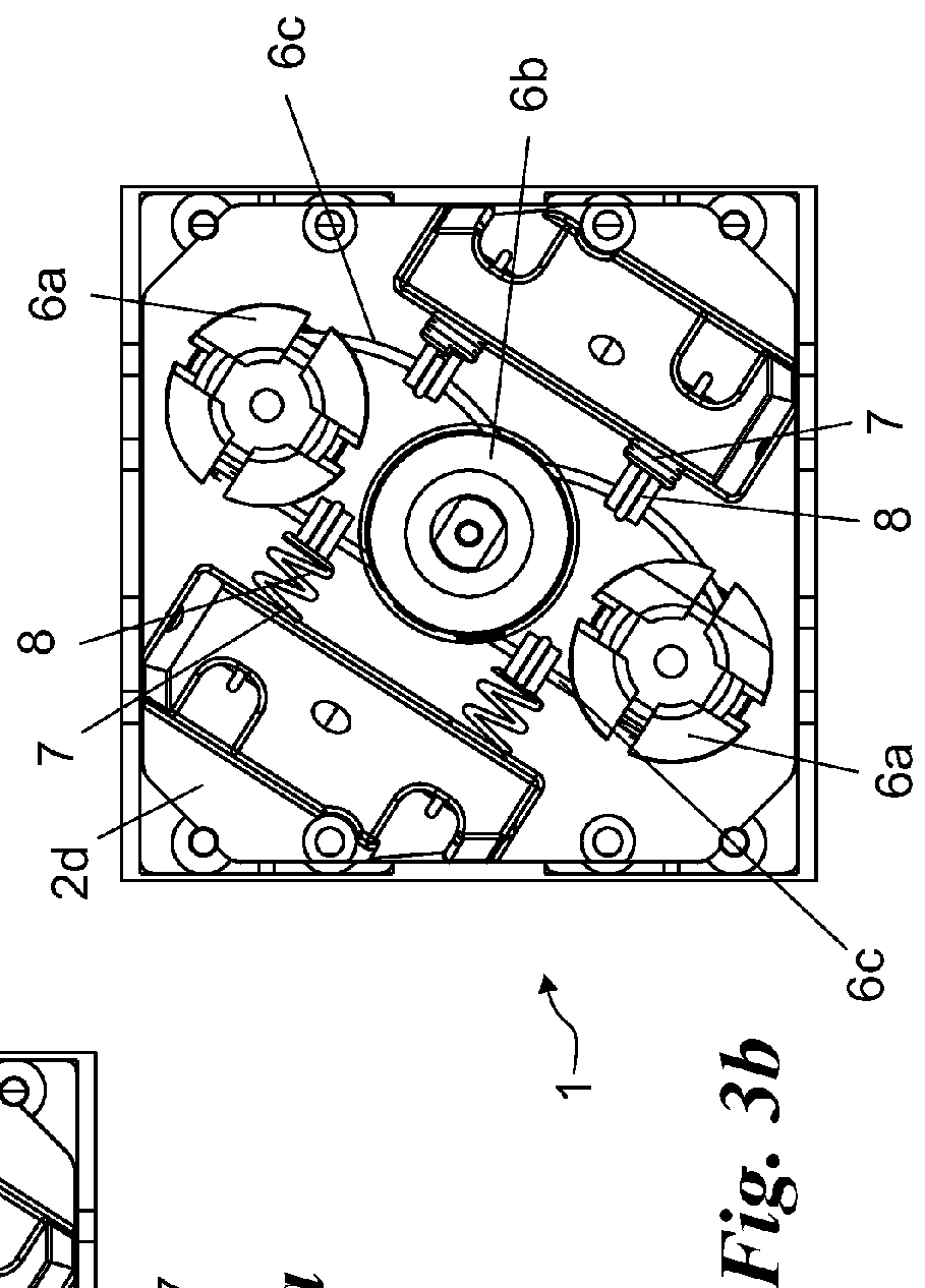
[0038]With reference to the drawings, the variable pliability actuator according to the invention is generally denoted at number 1.

[0039]It can be advantageously applied to a robot 100, i.e., a device adapted to be used in the industrial field for example, for handling and assembling operations. In particular, robot 100 is suitable to handle and assemble parts of reduced sizes, such as circuits. It is pointed out that also intended by the term “robot” is, in addition to the aforesaid devices, service and prosthesis robotics, that is to say mechanical devices adapted to replace a missing part of the body such as a limb, or to integrate a damaged part.

[0040]In particular, at least one variable pliability actuator 1 is located inside a robot 100 and, more specifically it is located intermediate between a pair of components that can be mutually moved. It is rigidly secured to an integral component 101 and moves a movable component 102 relative to the system made up of component 101 and ...


PUM


Abstract

A variable pliability actuator is provided to move a movable component including two electric rotary motors, at least one output shaft connected to be set in rotation by the motors around a rotation axis, an elastic transmission system to enable motion transfer from the motors to the output shaft and to vary the pliability the output shaft, a control unit to adjust at least the pliability of the output shaft through the elastic transmission system, and a holding structure to hold at least the motors, the elastic transmission system, the output shaft and the control unit. The holding structure has a driving output placed at the outer surface controlled by the output shaft and connected to set the movable component in rotation about the rotation axis, at least one stiff coupling element to enable a stiff connection of the holding structure, and a support output opposite the driving output, substantially coaxial with the rotation axis and partly housing and stabilizing the rotation of the movable component.

Description

FIELD OF THE INVENTION[0001]The present invention relates to a variable pliability actuator, of the type pointed out in the preamble of the first claim.[0002]It is of the type adapted to be used in a robot, or any other device equipped with suitable members capable of sensing the surrounding environment and interacting therewith. In particular, the actuator is disposed between two components of a robot in order to move said two components relative to each other, varying the pliability between them.[0003]Preferably, the variable pliability actuator is adapted to be used in all applications in which a person can be present within the robot's operating area or in the neighborhood thereof.[0004]It is therefore arranged in industrial robots used in operations concerning handling or assembling of components or disposed in orthopedic prosthesis, i.e., an apparatus adapted to replace one part of the human body, such as an arm or a leg for example. Finally, the actuator is adapted to be used...

Claims


Application Information

Patent Timeline
Patent Type & Authority Patents(United States)
IPC IPC(8): B25J17/00B25J17/02B25J18/00B25J9/10B25J9/08B25J19/06
CPCB25J19/068B25J9/08B25J9/10Y10T74/20317
Inventor BICCHI, ANTONIOCATALANO, MANUEL GIUSEPPEGARABINI, MANOLOGRIOLI, GIORGIO
Owner UNIV DI PISA CENT INTERDIPARTIMENTALE DI RICERCA E PIAGGIO
Why Eureka
Try Eureka