Method of measuring shear bond strength of cement

a technology of shear bond strength and cement, which is applied in the direction of measuring devices, instruments, scientific instruments, etc., can solve the problems of reducing the cost-effectiveness of wells, radial and longitudinal pipes expanding and/or contracting, and safety risks from pressure build-up

Active Publication Date: 2016-01-05
BAKER HUGHES INC
View PDF4 Cites 5 Cited by
  • Summary
  • Abstract
  • Description
  • Claims
  • Application Information

AI Technical Summary

Benefits of technology

[0018]Methods of using the testing apparatus employ a sample core of the targeted subterranean formation and simulate the equivalent spacing existing in-situ between the formation and annulus of a producing well. As such, use of the testing apparatus allows for an accurate measurement of shear bond strength at the actual interface of cement and formation as well as at the actual interface of cement and casing within the producing well of interest.

Problems solved by technology

Leakage behind the casing reduces the cost-effectiveness of the well and may cause safety risks from pressure build-up.
During well treatment operations, in particular completion and production phases of the well, variations in temperature and internal pressure of the wellbore pipe string may result in radial and longitudinal pipe expansion and / or contraction.
Such stresses lead to cracking and / or disintegration of the cement sheath.
Thus, failure of a cement sheath to provide zonal isolation may occur as a result of properties of the cement-casing interface, the cement-formation interface as well properties of the cement.
To date, however, neither a testing protocol nor an apparatus has been developed which is capable of measuring shear bond strength at both interfaces.

Method used


Image

  • Method of measuring shear bond strength of cement
  • Method of measuring shear bond strength of cement
  • Method of measuring shear bond strength of cement

Examples


example 1

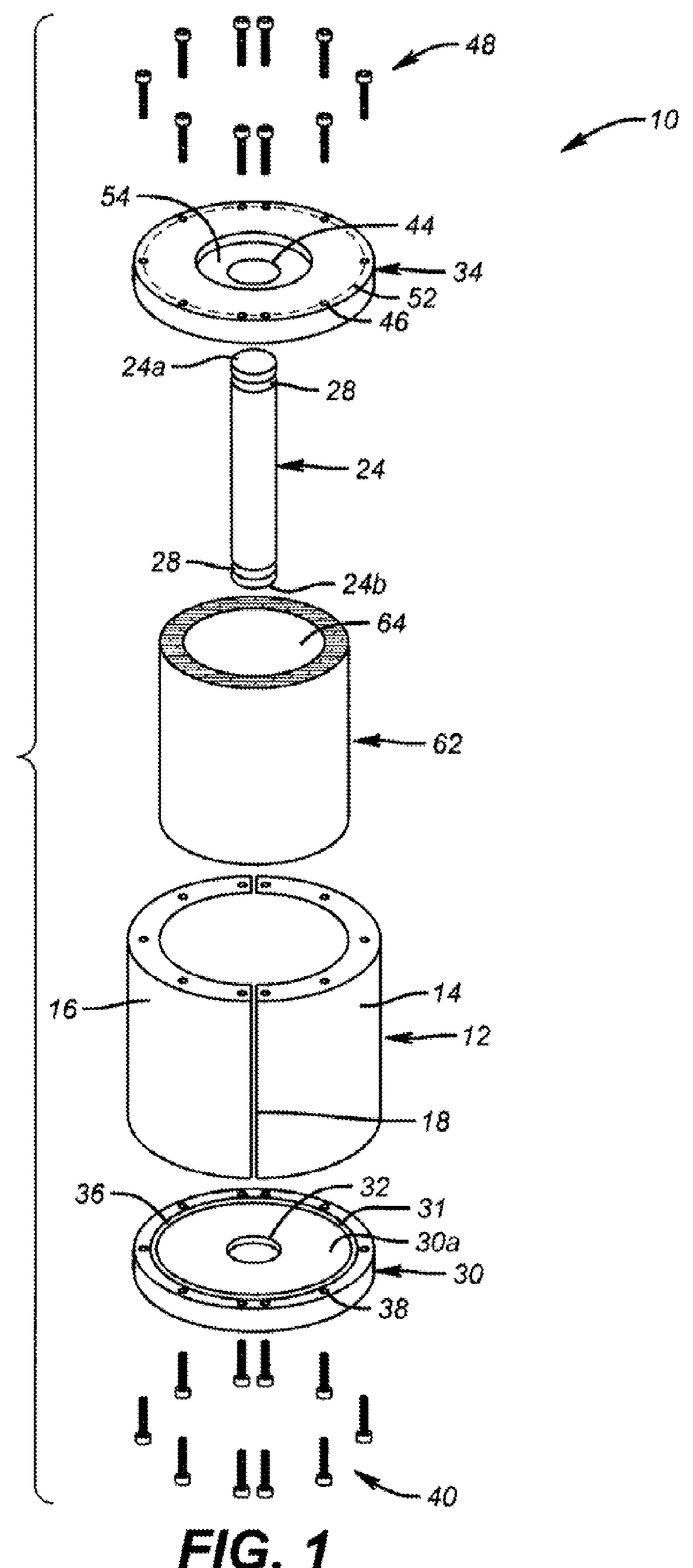
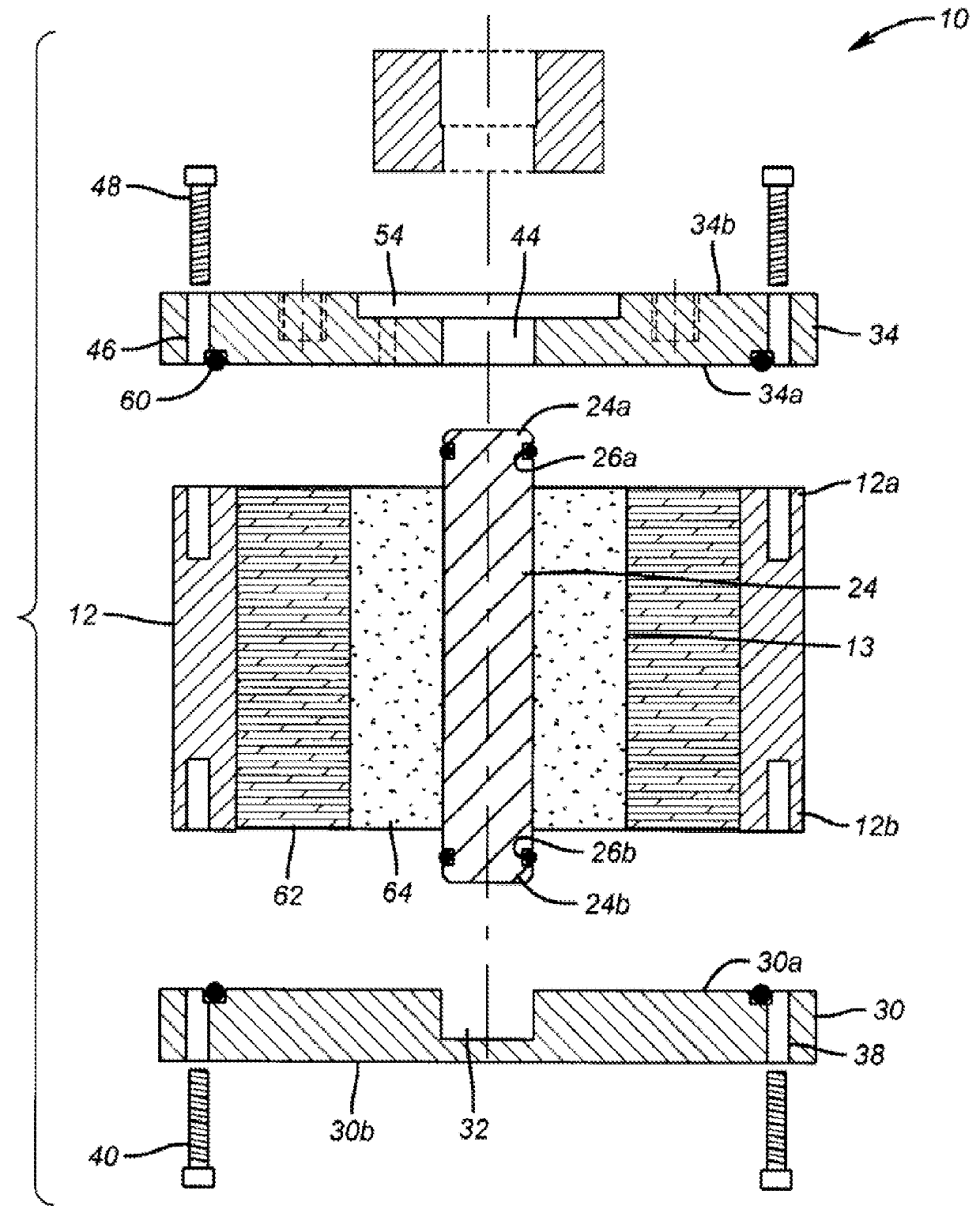
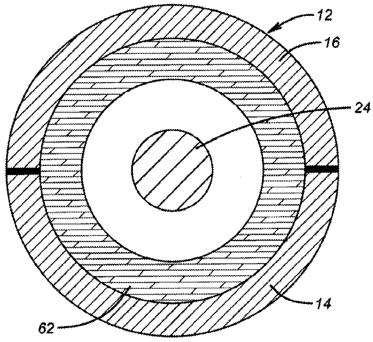
[0048]The inside diameter (CID) of a shale sample core from North Africa was measured to be 2.133 in. The outside diameter of a vertical rod (CROD) and the length of the vertical rod (CRL) were measured to be 0.75 in. and 3.78 in., respectively. Split body pieces 14 and 16 were secured to form a housing. O-ring 36 was inserted within the recessed grooves of base plate 30 and the base plate was secured to the housing after rubber gaskets and O-rings were lubricated with a moly grease. Vertical rod 24 having lubricated O-rings 28a and 28b within recessed areas was installed into the recess of base plate 30.

[0049]A cementitious slurry was prepared by mixing Portland Class G cement and fresh water at 15.8 pounds per gallon (ppg). To the slurry was mixed 35 wt. % of a 200-325 mesh silica flour; and 0.02 gallons per sack of cement (gps) of a liquid defoamer; 0.20 gps of a liquid cement dispersant; 1.46 gps of a liquid bonding agent; 0.39 gps of a liquid fluid loss control agent; and 0.10 ...


PUM

PropertyMeasurementUnit
outer diameteraaaaaaaaaa
thicknessaaaaaaaaaa
inner diameteraaaaaaaaaa

Abstract

An apparatus for determining shear bond strength of a cement to be set within a wellbore penetrating a subterranean formation consists of a housing, a vertical rod which extends from the uppermost portion of the housing through the lowermost portion of the housing, a base plate for positioning onto the bottom of the housing and for supporting the lowermost portion of the vertical rod, and a test plate for positioning onto the top of the housing through which the uppermost portion of the vertical rod extends. The apparatus may further contain a push rod. Shear bond strength is determined by introducing into the housing a sample core of the formation prior to introduction of a slurry containing the cement. The force required to break the bond between the vertical rod and the set cement may be used to determine the shear strength between the casing within the wellbore and the set cement when the cement is hardened within the wellbore. The force required to break the bond between the set cement and the sample core may be used to determine the shear strength between the set cement and formation core when the cement is hardened within the wellbore.

Description

FIELD OF THE INVENTION[0001]The invention relates to an apparatus for measuring the shear bond strength of a set cement to the face of a subterranean reservoir and to the face of the casing within the wellbore of the reservoir. The invention further relates to methods of using the testing apparatus and to methods of optimizing performance-based parameters in field operations.BACKGROUND OF THE INVENTION[0002]During construction of oil and gas wells, a rotary drill is typically used to bore through subterranean reservoirs of the earth to form a wellbore. As the rotary drill bores through the earth, a drilling fluid or mud is circulated through the wellbore. Drilling fluids are usually pumped from the surface into the wellbore through a drill string and transmitted to the drill bit. By continuously pumping the drilling fluid, the drilling fluid can be circulated out the bottom of the drill pipe and back up to the well surface through the annular space between the wall of the wellbore a...

Claims


Application Information

Patent Timeline
Patent Type & Authority Patents(United States)
IPC IPC(8): G01N3/00G01N33/38
CPCG01N33/383
Inventor SHINE, JR., JOSEPH MICHAELGO BONCAN, VIRGILIO C.MARTIN, ROBERTLANT, KEITHBUFORD, JR., CHARLES C.
Owner BAKER HUGHES INC
Why Eureka
Try Eureka