X-ray generating tube, X-ray generating apparatus and X-ray imaging system using the same

a technology of generating apparatus and generating tube, which is applied in the direction of x-ray tube windows, electrical devices, electric discharge tubes, etc., can solve the problems of complex valve shape, and achieve the effect of simple structure, improved withstand voltage properties of x-ray generating tubes, and high reliability

Inactive Publication Date: 2016-01-05
CANON KK
View PDF17 Cites 7 Cited by
  • Summary
  • Abstract
  • Description
  • Claims
  • Application Information

AI Technical Summary

Benefits of technology

[0007]It is an object of the present invention to improve withstand voltage property of an X-ray generating tube by a simple structure, and further to provide an X-ray generating apparatus and an X-ray imaging system having high reliability by using the X-ray generating tube having improved withstand voltage property.

Problems solved by technology

However, in this structure, in order to prevent a potential gradient in an area that is not covered with the electrical resistive film from being steep in a potential distribution on the outer surface of the valve, a complicated valve shape is required.

Method used


Image

  • X-ray generating tube, X-ray generating apparatus and X-ray imaging system using the same
  • X-ray generating tube, X-ray generating apparatus and X-ray imaging system using the same
  • X-ray generating tube, X-ray generating apparatus and X-ray imaging system using the same

Examples


example 1

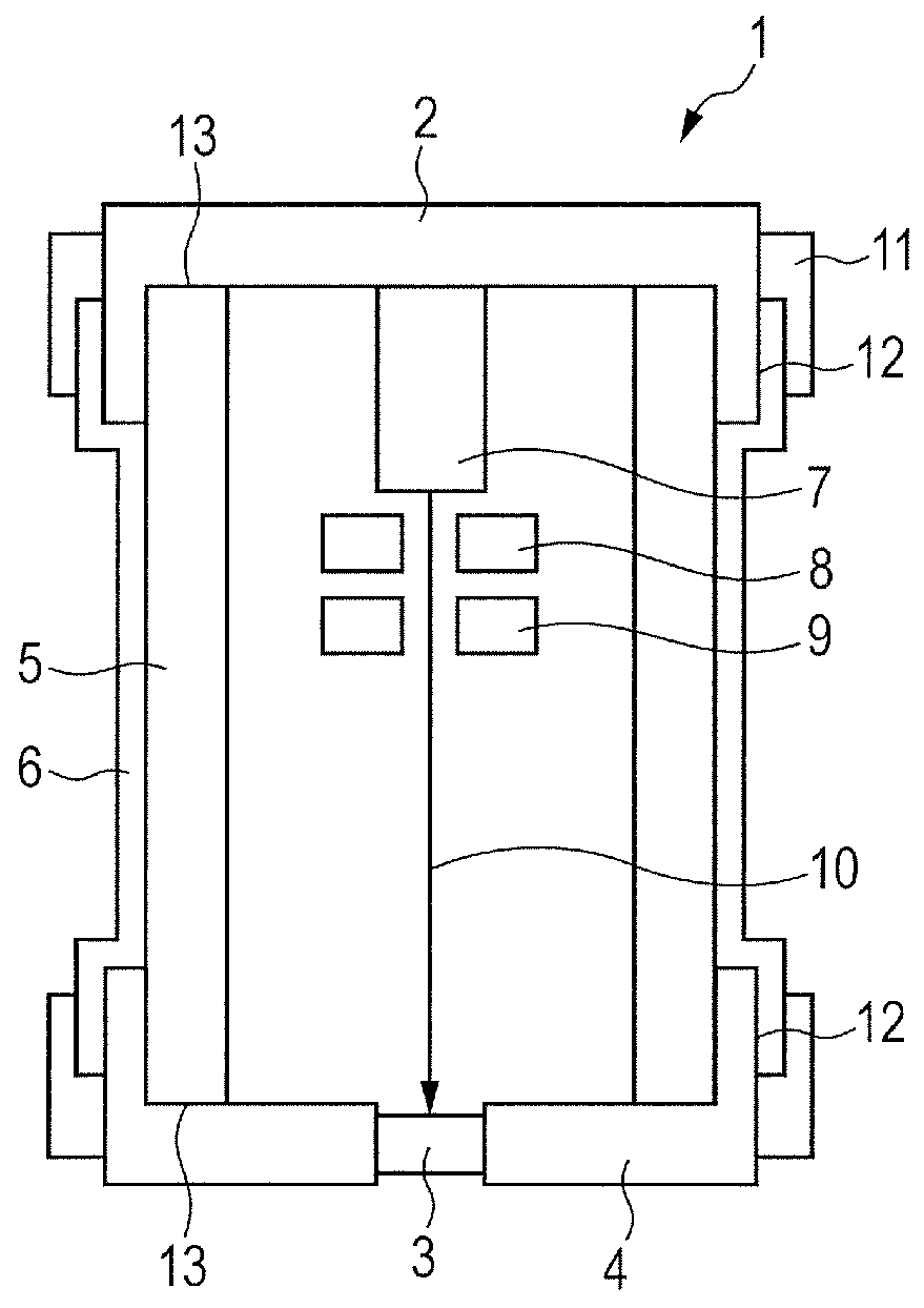
[0057]The X-ray generating tube 1 illustrated in FIG. 1A was manufactured.

[0058]Slurry liquid made of a solution containing powder Kovar glass and acetic acid as main ingredients was sprayed and applied onto the outer peripheral surface of the cylindrical insulating tube 5 made or alumina, and was melted and welded at a glazing temperature of 1,000° C. so as to form the resistive film 6.

[0059]Next, the insulating tube 5 was sealed with the anode 4 made of Kovar metal with the target 3 mounted thereon and the cathode 2 made of Kovar metal with the electron emitting source 7 by using silver braze at 900° C. After that, the extending portions of the anode 4 and the cathode 2 were swaged toward the insulating tube 5 by an external force so that the anode 4 and the cathode 2 were electrically connected to the resistive film 6 at the extending portions overlapping the end portions of the resistive film 6.

[0060]An electric field was applied to the X-ray generating tube 1 having the above-m...

example 2

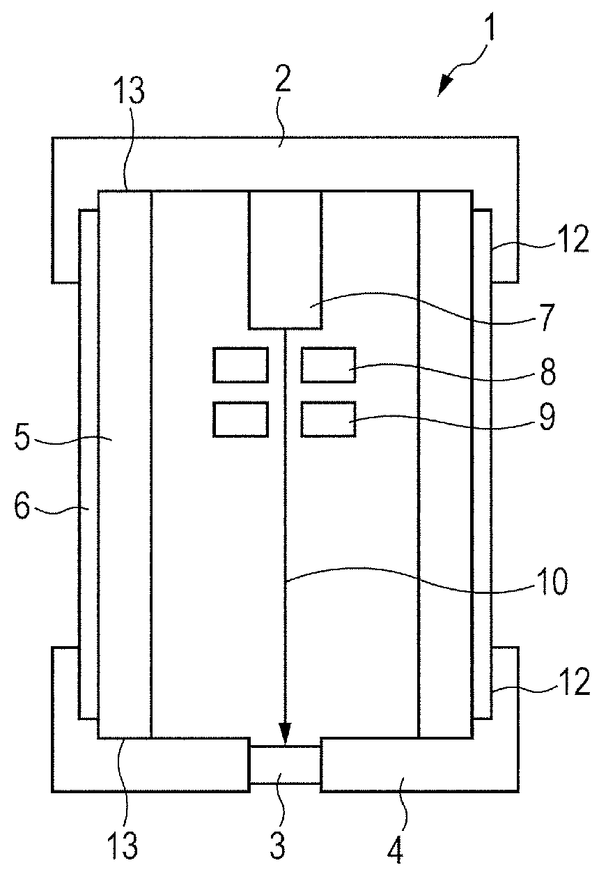
[0064]The X-ray generating tube 1 illustrated in FIG. 1B was manufactured.

[0065]The cylindrical insulating tube 5 made of alumina was sealed with the anode 4 made of Kovar metal with the target 3 mounted thereon and the cathode 2 made of Kovar metal with the electron emitting source 7 mounted thereon by using copper braze at 1,050° C. After that, the resistive film 6 similar to that of Example 1 was formed on the outer peripheral surface of the insulating tube 5 so that each end thereof overlapped with a portion of the extending portion of the anode 4 or the cathode 2. Further, the conductive paste 11 was applied onto the portions of the resistive film 6 where the extending portion of the anode 4 or the cathode 2 was overlapped so that end portions of the resistive film 6 were covered.

[0066]Next, the IV characteristics of the insulating tube 5 and the resistive film 6 were measured for the X-ray generating tube 1 having the structure described above similarly to Example 1, the sheet...


PUM

PropertyMeasurementUnit
dark currentaaaaaaaaaa
voltageaaaaaaaaaa
temperaturesaaaaaaaaaa

Abstract

Provided is an X-ray generating tube with improved withstand voltage property by a simple structure, the X-ray generating tube including a cathode connected to one opening of an insulating tube and an anode connected to the other opening, in which a resistive film having a lower sheet resistance value than that of the insulating tube is disposed on an outer periphery of the insulating tube, and the cathode and the anode are electrically connected to each other via the resistive film.

Description

BACKGROUND OF THE INVENTION[0001]1. Field of the Invention[0002]The present invention relates to an X-ray generating tube, and an X-ray generating apparatus and an X-ray imaging system including the X-ray generating tube, which can be used for a medical equipment, a nondestructive inspection apparatus, and the like, for example.[0003]2. Description of the Related Art[0004]In general, an X-ray generating tube accelerates electrons emitted from an electron emitting source with use of a tube voltage in a vacuum and irradiates a target made of a metal such as tungsten with the electron so as to generate X-ray. The tube voltage set in the X-ray generating tube is approximately 100 kV, for example, and the X-ray generating tube is required to have a structure that can withstand the high voltage.[0005]In Japanese Patent Application Laid-Open No. 2009-245806, there is disclosed a technology for stably suppressing breakdown of a valve due to a discharge by applying an electrical resistive fi...

Claims


Application Information

Patent Timeline
Patent Type & Authority Patents(United States)
IPC IPC(8): H01J35/16G01N23/04H01J35/18
CPCH01J35/18H01J2235/186G01N23/04H01J35/06H01J35/116H01J35/186H01J2235/18
Inventor YANAGISAWA, YOSHIHIROSATO, YASUEUKIYO, NORITAKASANDO, KAZUHIRO
Owner CANON KK
Why Eureka
Try Eureka