
Systems and methods to synchronize commands sent to a multi-electrode lead (MEL) with a portion of a cardiac pacing cycle

a multi-electrode lead and synchronization technology, applied in the field of implantable cardiac systems and leads, can solve problems such as pacing and/or sensing, and achieve the effect of preventing commands

Inactive Publication Date: 2016-01-12
PACESETTER INC
View PDF20 Cites 1 Cited by
  • Summary
  • Abstract
  • Description
  • Claims
  • Application Information

AI Technical Summary

Benefits of technology

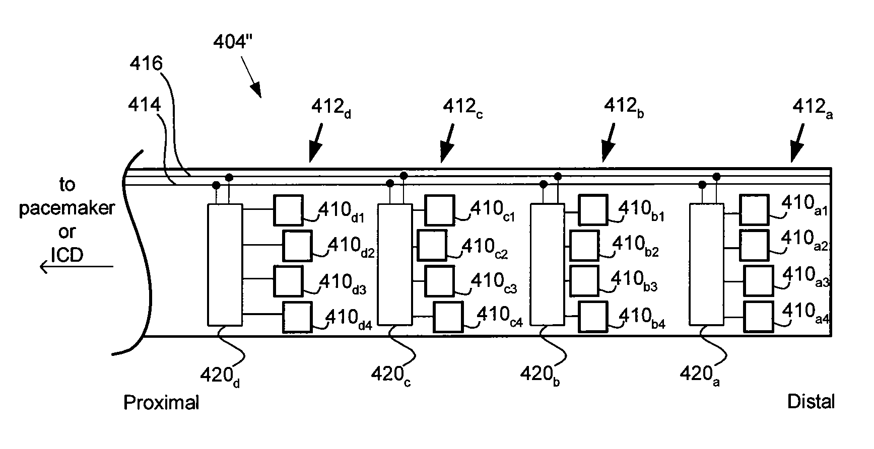
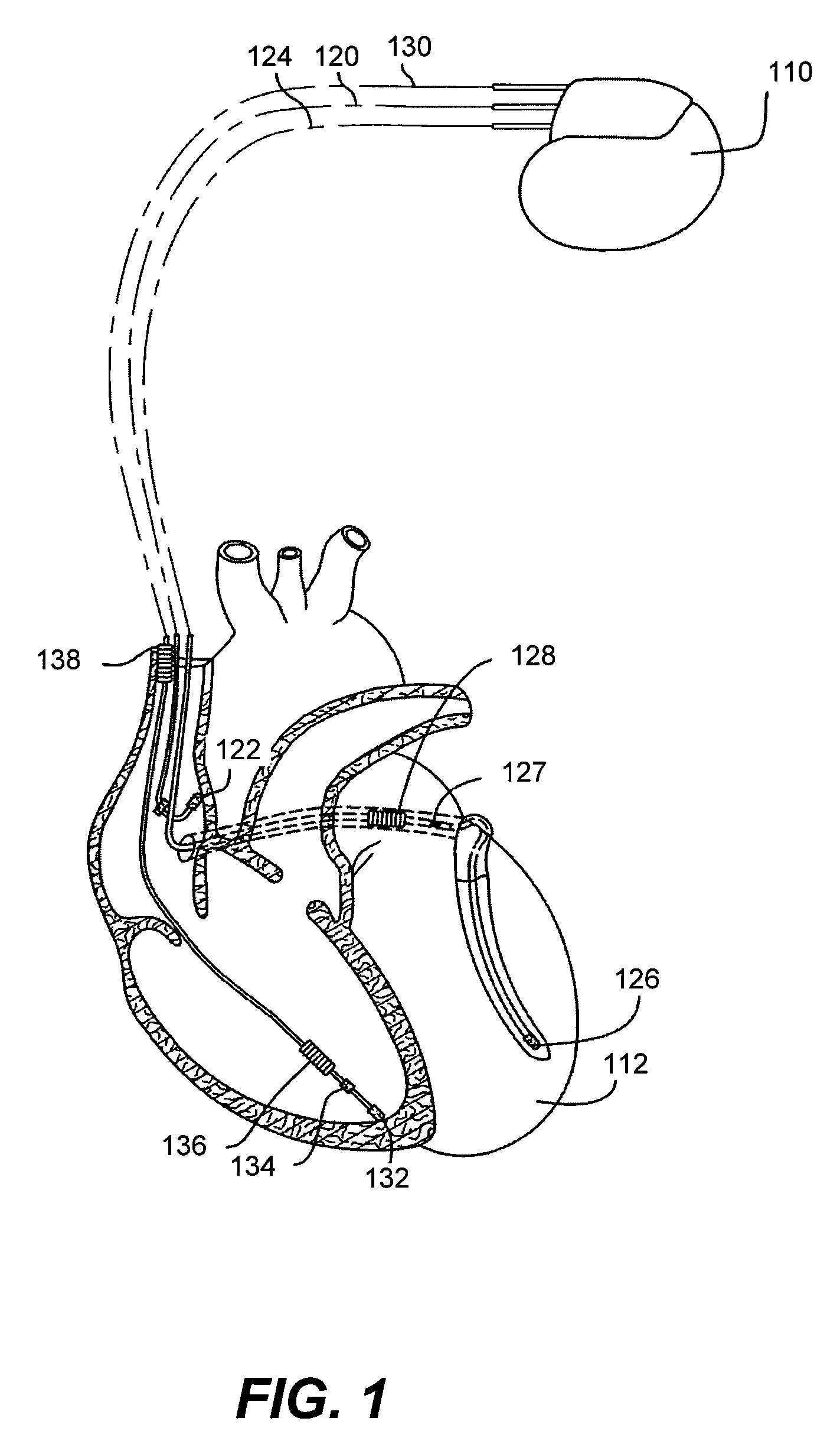
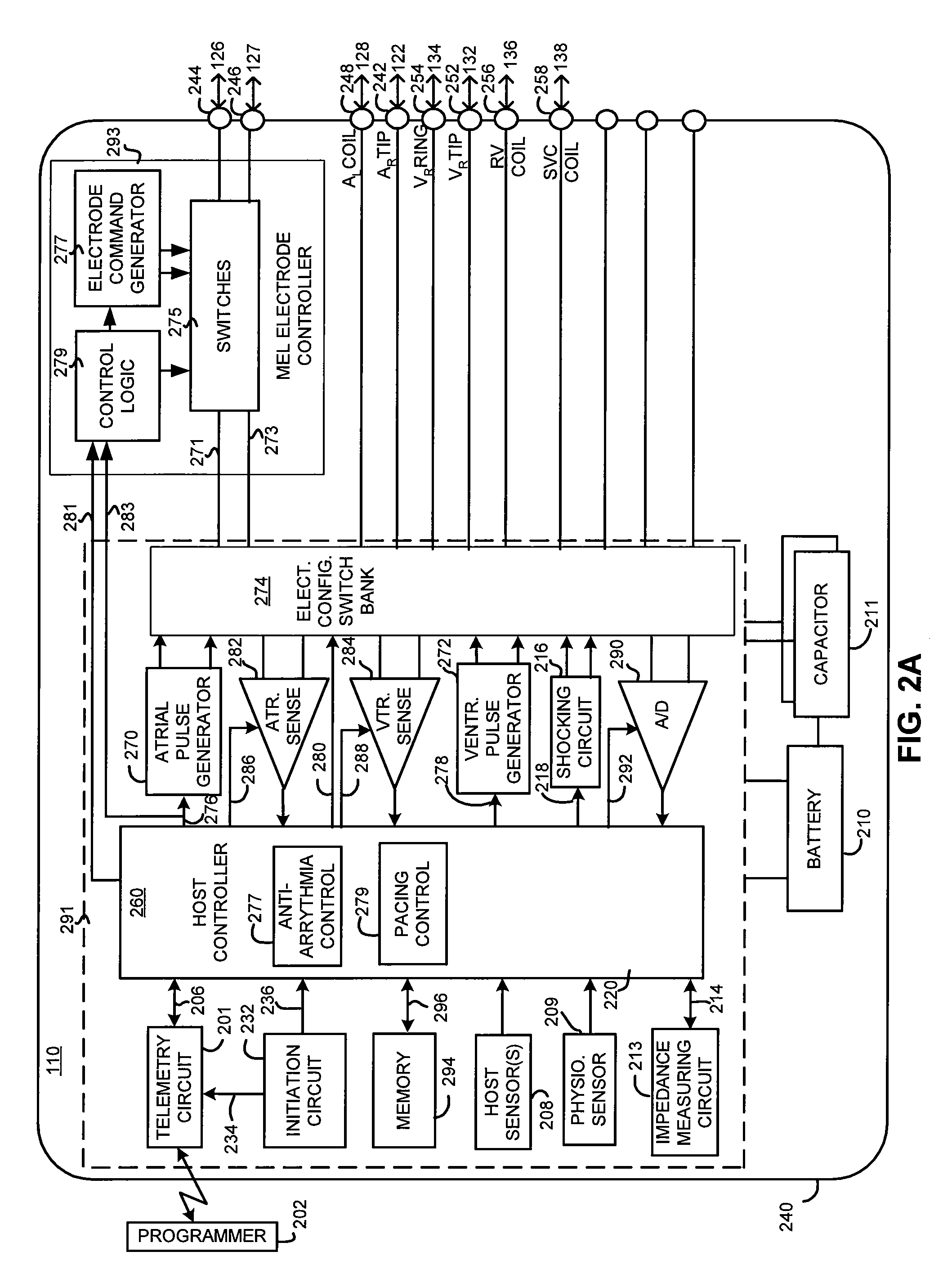
[0011]In one embodiment of the present invention, the one or more commands are sent to control circuitry within the MEL during a predetermined portion of a cardiac pacing cycle. This avoids the problems of the prior systems that were not synchronized with the cardiac pacing cycle, since, in the present invention, the one or more commands can be sent when they would not interfere with the pacing and / or sensing.
[0012]In one embodiment, the one or more commands are sent to the control circuitry of the MEL when cardiac tissue is refractory from a cardiac pacing pulse. This prevents the commands from undesirably stimulating cardiac tissue. In prior system, commands sent when the cardiac tissue is not refractory can potentially inadvertently cause capture.
[0013]The sending of the commands can occur such that the one or more commands are sent between instances when sensing circuitry of the implantable cardiac stimulation device is being used to obtain one or more signals indicative of cardiac electrical activity. Sending the one or more commands at this time prevents the commands from interfering with the sensed signals.

Problems solved by technology

This can cause problems since the commands can accidently interfere with the pacing and / or sensing.
In prior system, commands sent when the cardiac tissue is not refractory can potentially inadvertently cause capture.

Method used


Image

  • Systems and methods to synchronize commands sent to a multi-electrode lead (MEL) with a portion of a cardiac pacing cycle
  • Systems and methods to synchronize commands sent to a multi-electrode lead (MEL) with a portion of a cardiac pacing cycle
  • Systems and methods to synchronize commands sent to a multi-electrode lead (MEL) with a portion of a cardiac pacing cycle

Examples


Embodiment Construction

[0024]The following description is of the best modes presently contemplated for practicing various embodiments of the present invention. The description is not to be taken in a limiting sense but is made merely for the purpose of describing the general principles of the invention. The scope of the invention should be ascertained with reference to the claims. In the description of the invention that follows, like numerals or reference designators will be used to refer to like parts or elements throughout. In addition, the first digit of a reference number identifies the drawing in which the reference number first appears.

[0025]It would be apparent to one of skill in the art reading this description that the various embodiments of the present invention, as described below, may be implemented in many different embodiments of hardware, software, firmware, and / or the entities illustrated in the Figures. Any actual software, firmware and / or hardware described herein is not limiting of the...


PUM


Abstract

Embodiments of the present invention concern the timing of sending one or more commands to control circuitry of a multi-electrode lead (MEL). In one embodiment, the one or more commands are sent to control circuitry within the MEL during a predetermined portion of a cardiac pacing cycle to avoid potential problems of prior systems that were not synchronized with the cardiac pacing cycle. In one embodiment, the one or more commands are sent when cardiac tissue is refractory from a cardiac pacing pulse, to prevent the command(s) from potentially undesirably stimulating cardiac tissue. The command sending can occur such that the one or more commands are sent between instances when sensing circuitry of the implantable cardiac stimulation device is being used to obtain one or more signals indicative of cardiac electrical activity, to prevent interference between the one or more commands with the signals indicative of cardiac electrical activity that are sensed.

Description

PRIORITY CLAIM[0001]This application claims priority under 35 U.S.C. §119(e) to U.S. Provisional Patent Application No. 61 / 234,945, filed Aug. 8, 2009, which is incorporated herein by reference.FIELD OF THE INVENTION[0002]Embodiments of the present invention relate to implantable cardiac systems and leads for use therewith. More specifically, embodiments of the present invention relate to systems and methods using a Multi-Electrode Lead (MEL).BACKGROUND OF THE INVENTION[0003]In the normal human heart, the sinus node, generally located near the junction of the superior vena cava and the right atrium, constitutes the primary natural pacemaker initiating rhythmic electrical excitation of the heart chambers. The cardiac impulse arising from the sinus node is transmitted to the two atrial chambers, causing a depolarization known as a P-wave and the resulting atrial chamber contractions. The excitation pulse is further transmitted to and through the ventricles via the atrioventricular (A-...

Claims


Application Information

Patent Timeline
Patent Type & Authority Patents(United States)
IPC IPC(8): A61N1/00A61N1/368A61N1/37A61N1/39
CPCA61N1/368A61N1/3686A61N1/3684A61N1/3704A61N1/3912A61N1/36842
Inventor SHELCHUK, ANNEWU, YONGJIANPONTIGA, CHRISPIXLEY, APRILIRANITALAB, PAJHANDCLEM, ELISABETH M.HOSSAIN, SHOHANYI, JIANCHUN
Owner PACESETTER INC
Learn More