Conical nib and writing instrument using the same

a writing instrument and pen body technology, applied in the direction of nibs, printing, ink reservoir pens, etc., can solve the problems of low wear resistance of the nib, easy wear of the nib as compared with metal or ceramic ones, etc., to achieve the effect of extending the life of the nib or the writing instrument, high elasticity, and variation in the width of written lines

Active Publication Date: 2016-01-12
YAMANAKA SHIZUO
View PDF9 Cites 0 Cited by
  • Summary
  • Abstract
  • Description
  • Claims
  • Application Information

AI Technical Summary

Benefits of technology

[0010]With the structure described above, since the nib is made of the synthetic resin material in which engineering plastic, among other plastic, is used, the writing instrument of the present invention is wear resistant and, therefore, duration of the nib or the writing instrument can be extended. Further, since the nib is highly elastic while it is made of a hard material, significant effects can be produced in that, for example, variation in writing pressure at, such as stop, hook and fade in writing characters, can express variation in the width of the written lines.

Problems solved by technology

However, writing instruments with such plastic conical nibs have a problem that wear resistance at the nibs is low and the nibs wear easily as compared with metal or ceramic ones.

Method used


Image

  • Conical nib and writing instrument using the same
  • Conical nib and writing instrument using the same
  • Conical nib and writing instrument using the same

Examples


first embodiment

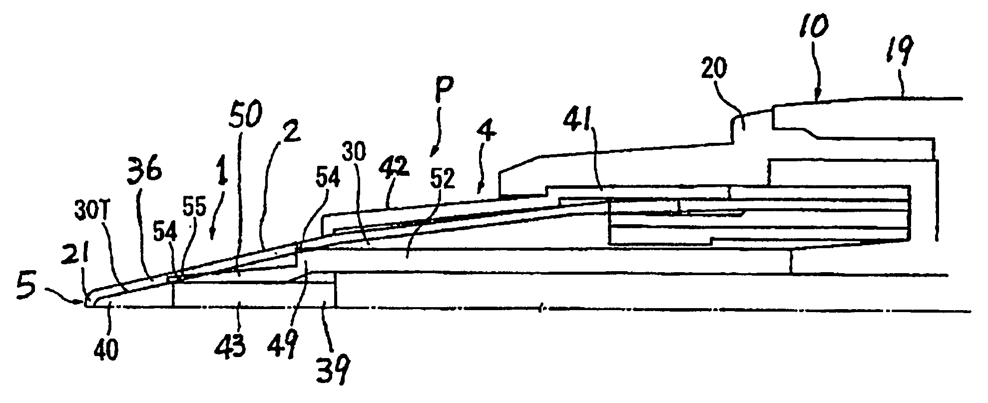
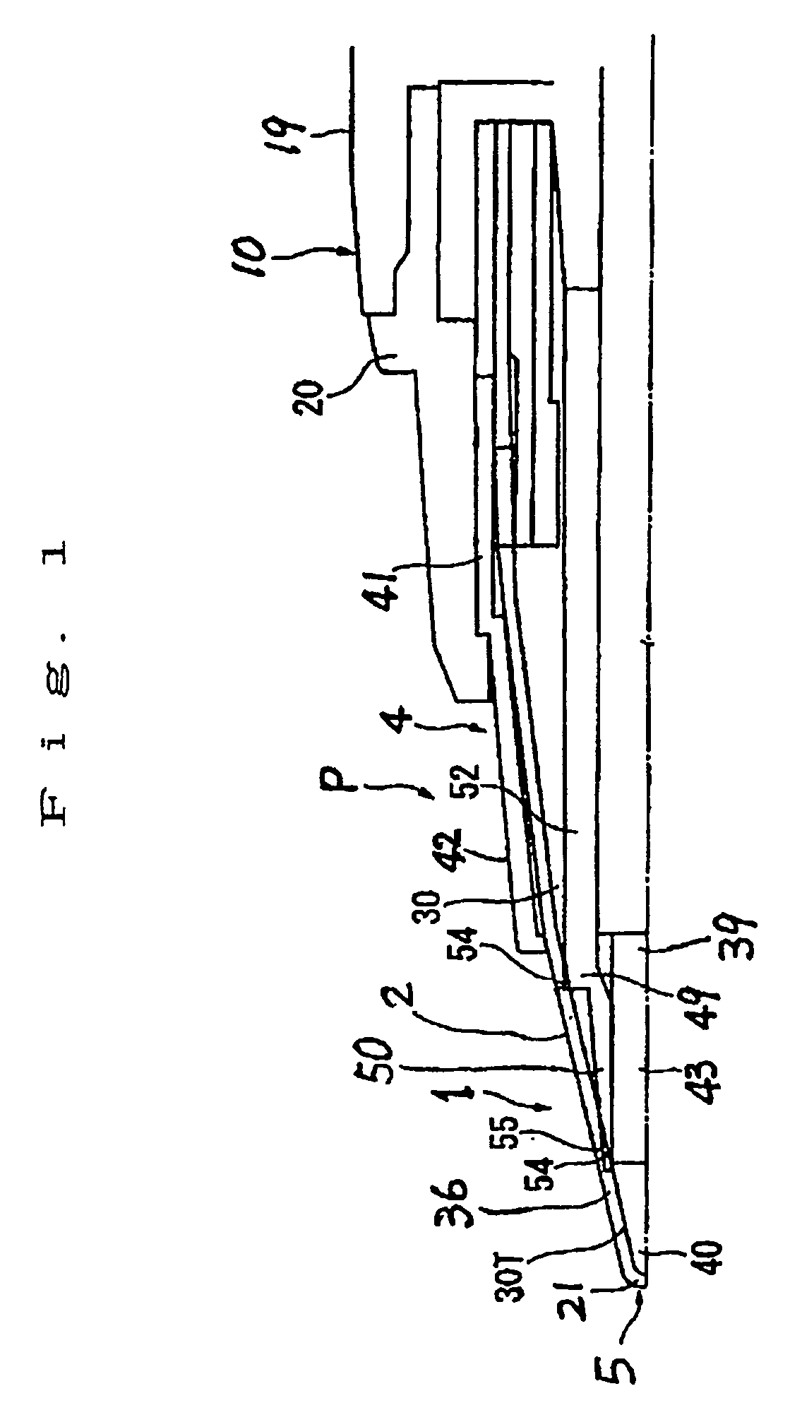
[0034]Hereinafter, a first embodiment of the invention will be described with reference to FIG. 1, and FIGS. 2 to 4 as needed. FIG. 1 illustrates a main part of a writing instrument. As illustrated in FIG. 1, a writing instrument P includes a pen shaft 10 and a conical nib 1. The nib 1 is connected to ink contained in the pen shaft 10 via an ink supply wick 39 which has a capillary action. The pen shaft 10 is made of, for example, a plastic material into a tubular shape, such as a cylindrical shape. The pen shaft 10 includes a shaft cylinder 19 of which a mouth piece (which is a tubular piece for fixing the nib 1) 20 is attached at a tip and a rear end is closed and an ink reservoir (not illustrated throughout the drawings) which is formed in an integrated manner inside the shaft cylinder 19. The nib 1 is inserted in the mouth piece 20 at the tip of the shaft cylinder 19 and the ink supply wick 39 is inserted in and disposed inside the shaft cylinder 19 on the tip side thereof. With...

second embodiment

[0048]Next, a second embodiment of the present invention will be described with reference to the attached drawings. In this second embodiment, the structure of the nib in which the combtooth-shaped pieces and the base portion are provided separately in the above-described first embodiment will be described in more detail.

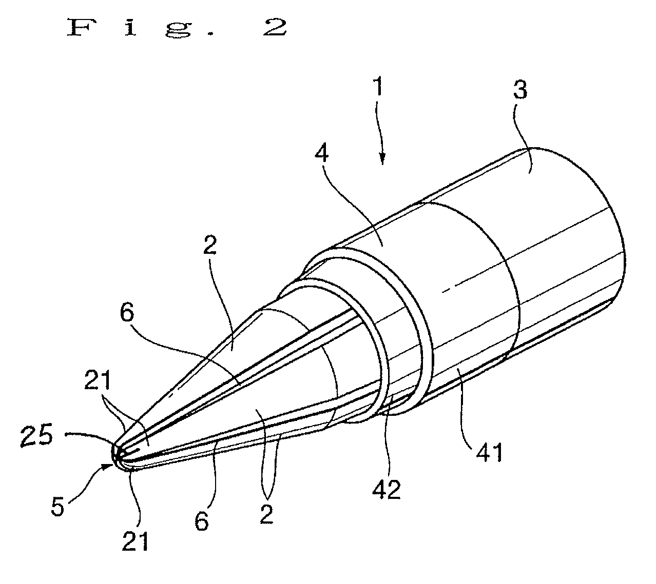
[0049]FIG. 5 is a perspective view of a conical nib according to the second embodiment of the present invention. In FIG. 5, 1 denotes a conical nib (hereafter, referred to as “nib”) which includes a plurality of combtooth-shaped pieces 2, a holder member 3 and a converging member 4. The plurality of combtooth-shaped pieces 2 are assembled to form a conical nib shape by the holder member 3 and the converging member 4. A writing tip 5 is formed at a tip and ink feed paths 6 are formed between adjacent combtooth-shaped pieces 2. The combtooth-shaped pieces 2 in this embodiment are, like those of the first embodiment, made of engineering plastic. The holder member 3 and...


PUM


Abstract

A nib, among other parts which constitute a writing instrument, is made of a synthetic resin material in which engineering plastic is used. An ink supply wick includes a wick cover. An outer shape of a wick cover is determined such that it is attached to an outer periphery of the ink supply wick between the nib and the ink supply wick and is made to closely adhere to an inner periphery of the nib at least at the tip of the nib. A space between the nib and the ink supply wick is filled with the wick cover. The nib is made of a synthetic resin material in which engineering plastic is used. Therefore, the nib wear resistant and duration of the nib or the writing instrument can be extended.

Description

BACKGROUND OF THE INVENTION[0001]1. Field of the Invention[0002]The present invention relates to a conical nib and a writing instrument using the same. More particularly, the invention relates to a wear-resistant conical nib and a writing instrument using the same.[0003]2. Description of the Related Art[0004]A writing instrument which includes such a kind of conical nib is disclosed in Japanese Unexamined Patent Application, First Publication No. H9-156279. In the disclosed writing instrument, the nib includes a nib base body and a converging member. The nib base body includes a cylindrical base portion and five to eight combtooth-shaped pieces. The combtooth-shaped pieces, each having a circular arc cross section, protrude from one end of the base portion in a continuous manner. The combtooth-shaped pieces are arranged at equal intervals around the circumference of a shaft with slit-shaped grooves formed therebetween. A hemispherical split portion is formed at tips of the combtooth...

Claims


Application Information

Patent Timeline
Patent Type & Authority Patents(United States)
IPC IPC(8): B43K1/00B43K1/02B43K8/00B43K17/02
CPCB43K1/003B43K1/02B43K8/00B43K17/02
Inventor YAMANAKA, SHIZUO
Owner YAMANAKA SHIZUO
Why Eureka
Try Eureka