Apparatus, X-ray irradiation method, and structure manufacturing method
a technology of x-ray irradiation and apparatus, applied in the direction of instruments, nuclear engineering, x-ray tubes, etc., can solve the problem of reducing detection accuracy, and achieve the effect of restricting the decrease of detection accuracy
- Summary
- Abstract
- Description
- Claims
- Application Information
AI Technical Summary
Benefits of technology
Problems solved by technology
Method used
Image

Examples
first embodiment
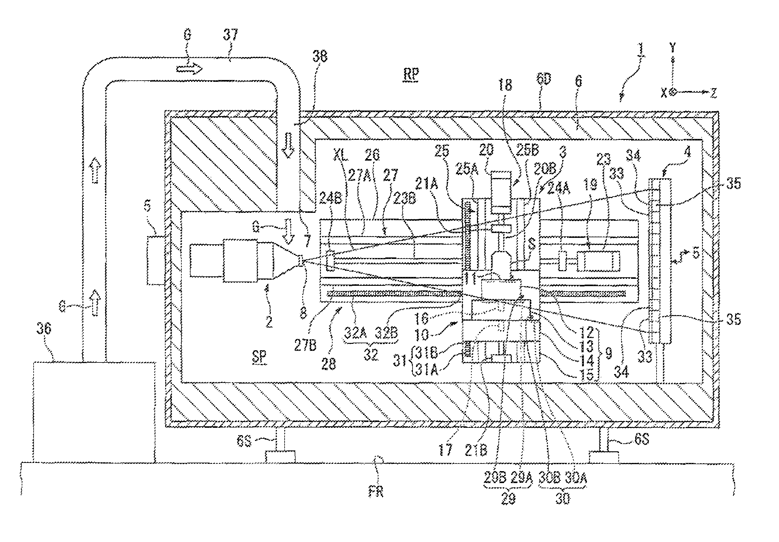
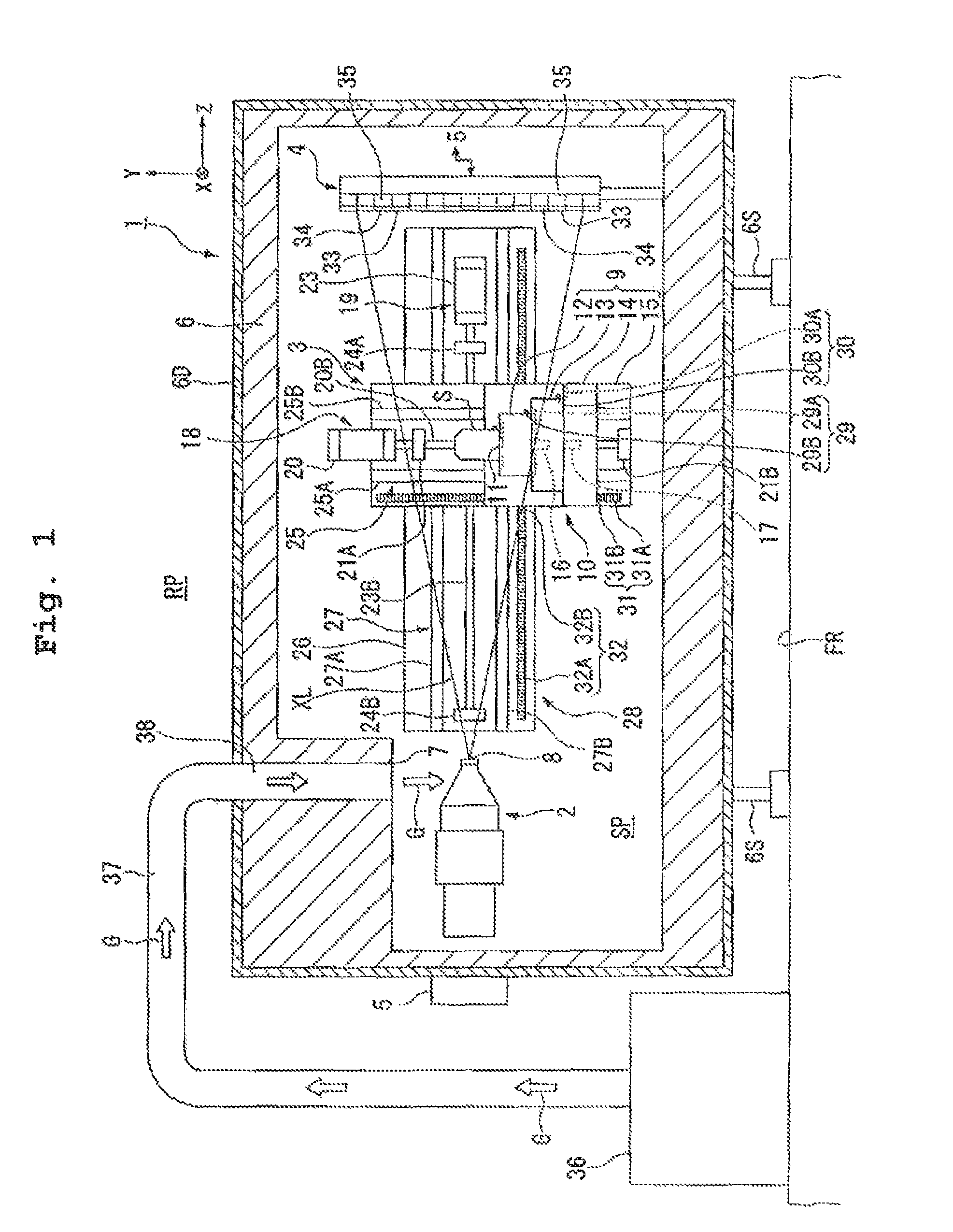
[0036]Further, in the first embodiment, the detection apparatus 1 includes a supply port 7 supplying a temperature-control led gas G to at least part of the X-ray source 2. The supply port 7 is arranged in the internal space SP.
[0037]In the first embodiment, the chapter member 6 is arranged on a support surface FR. The support surface FP, includes floor surfaces in a factory or the like. The chamber member 6 is supported by a plurality of support members 6S. The chamber member 6 is arranged on the support surface FR via, the support members 6S. In the first embodiment, the support members 6S separate the lower surface of the chamber member 6 from the support surface FR. That is, an inter space is formed between the lower surface of the chamber member 6 and the support surface FR. Further, it is also possible for at least part of the lower surface of the chamber member 6 to contact with the support surface FR.
[0038]The first embodiment, the chamber member 6 contains lead. The chamber...
second embodiment
[0122]The chamber member 6 has a duct 44. The duct 44 is formed to link the internal space SP and the external space RP. The opening at one end of the duct 44 is arranged to front on the internal space SP. The opening at the other end of the duct 44 is arranged to front on the external space RP. In the second embodiment, the opening at the one end of the duct 44 functions as the discharge port 43. At least part of the gas an the internal space SP is discharged from the discharge port 43 and, after flowing through the duct 44, let out to the external space RP via the opening at the other end of the duct 44.
[0123]In the second embodiment, the opening at the other end of the duct 44 is connected with one end of a duct 45. The other end of the duct 45 is connected to the adjusting device 36. In the second embodiment, the gas discharged from the discharge port 43 is sent to the adjusting device 36 through the flow passage of the duct 44 and duct 45 of the chamber member 6.
[0124]In the se...
third embodiment
[0138]Next, a third embodiment will be explained, in the following explanations, the same reference numerals will be assigned to the constitutive parts or components which are the same as or equivalent to those of the embodiments described above, and the explanations of which will be simplified or omitted.
[0139]FIG. 7 is a view showing part of a detection apparatus 1 in accordance with the third embodiment. Further, in the following explanations, while it is exemplified that the supply port 7 is arranged on the +Y side of the X-ray source 2 and the discharge port 43 is an or the −Y side, as described above, however, it is possible to arbitrarily determine the number and position of the supply ports 7 and discharge ports 43. Further, it is also possible to leave out the discharge port 43.
[0140]In FIG. 7, the detection apparatus 1 includes a temperature sensor 46 detecting the temperature of at least one of the X-ray source 2 and the internal space SP. In the third embodiment, the tem...
PUM
| Property | Measurement | Unit |
|---|---|---|
| wavelength | aaaaa | aaaaa |
| energy | aaaaa | aaaaa |
| energy | aaaaa | aaaaa |
Abstract
Description
Claims
Application Information