
Power control device

a power control device and power supply technology, applied in the direction of logic circuit coupling/interface arrangement, pulse technique, instruments, etc., can solve problems such as unplanned leakage curren

Active Publication Date: 2016-01-12
SK HYNIX INC
View PDF4 Cites 8 Cited by
  • Summary
  • Abstract
  • Description
  • Claims
  • Application Information

AI Technical Summary

Benefits of technology

The power control device described in this patent has two power-supply sources that generate different voltages. The device also has a power driver that creates an internal power source during the initial power-up period, regardless of which power-supply source is used. The technical effect of this invention is that it allows for more flexible and efficient power control during the initial power-up period, which can improve the overall performance and reliability of the power control device.

Problems solved by technology

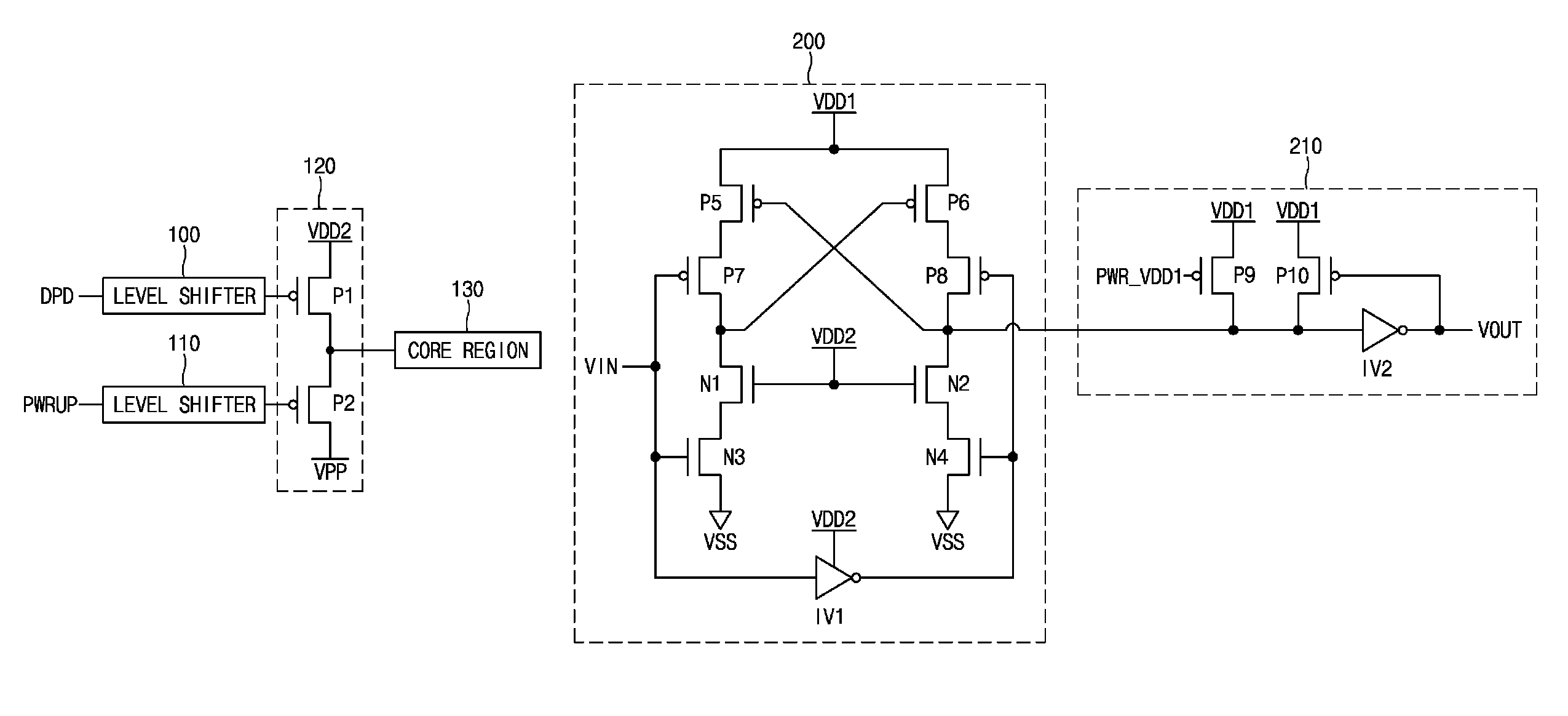
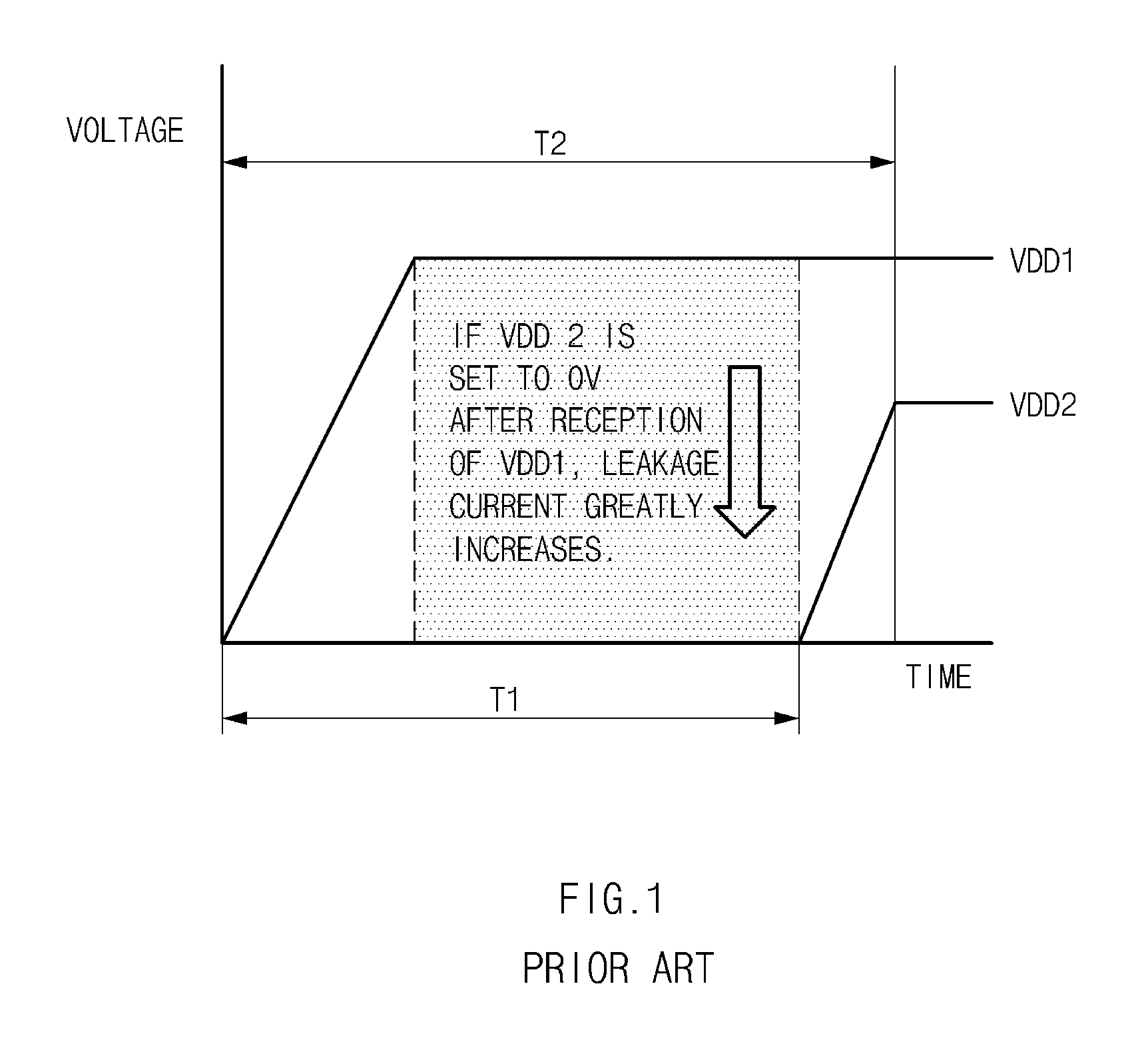
However, before the power-supply voltage VDD1 is ramped up and the power-supply VDD2 is ramped up, an undesired leakage current occurs.

Method used


Image

  • Power control device
  • Power control device
  • Power control device

Examples


Embodiment Construction

[0017]Reference will now be made in detail to the various embodiments, examples of which are illustrated in the accompanying drawings. Wherever possible, the same reference numbers are used throughout the drawings to refer to the same or like portions. In the following description, a detailed description of related known configurations or functions incorporated herein may be omitted for clarity of the subject matter of the various embodiments.

[0018]As semiconductor devices have been rapidly developed to implement higher integration and higher speed, the operation for correctly generating and efficiently distributing a level or category of the external power-supply voltage and a voltage needed for internal parts of the semiconductor devices is of importance to semiconductor technologies.

[0019]Multiple external power-supply voltages have been widely used in semiconductor memory devices such as dynamic random access memories (DRAMs) embedded in mobile electronic systems such as a lapto...


PUM


Abstract

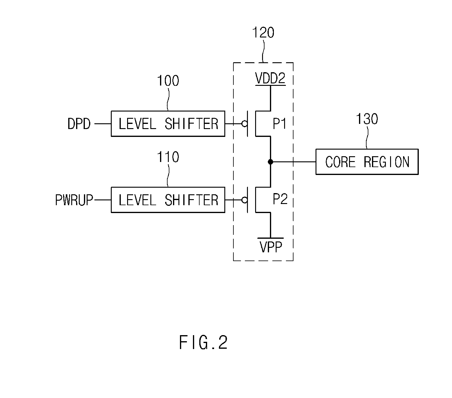
A power control device may include a first power-supply voltage source configured to generate a first power-supply voltage, and a second power-supply voltage source configured to generate a second power-supply voltage having a voltage level different from that of the first power-supply voltage. The power control device may include a power driver configured to provide an internal power source in response to the second power-supply voltage, irrespective of the first power-supply voltage source and the second power-supply voltage source, during an initial power-up period.

Description

CROSS-REFERENCE TO RELATED APPLICATION[0001]This application claims priority based upon Korean patent application No. 10-2014-0113460, filed on Aug. 28, 2014, the disclosure of which is hereby incorporated in its entirety by reference herein.BACKGROUND OF THE INVENTION[0002]1. Technical Field[0003]Embodiments of the present invention generally relate to a power control device, and more particularly to a technology for cutting off an unnecessary leakage current path when power of an integrated circuit (IC) having heterogeneous power is ramped up.[0004]2. Related Art[0005]Generally, a power-up signal generation circuit of a semiconductor device indicates a circuit for initializing a semiconductor device. In order to operate the semiconductor device, the power-up signal generation circuit receives an external voltage (VDD) from an external part. The voltage level of the external voltage (VDD) starts from 0V and increases up to a target voltage level at a predetermined slope.[0006]In th...

Claims


Application Information

Patent Timeline
IPC IPC(8): G05F1/10H03K17/687H03K19/185H03K19/0185
CPCH03K17/687H03K19/018521H03K3/356104
Inventor HONG, YUN, SEOK
Owner SK HYNIX INC
Learn More