Tuneable AWG device for multiplexing and demultiplexing signals and method for tuning said device

a technology of multiplexing and demultiplexing signals, applied in the direction of instruments, optical waveguide light guides, optics, etc., can solve the problems of inability to achieve immediate temperature changes, long transition time, and application itself admits that is not feasible, and patent application does not disclose a solution

Active Publication Date: 2016-01-19
UNIV POLITECNICA DE VALENCIA +2
View PDF3 Cites 3 Cited by
  • Summary
  • Abstract
  • Description
  • Claims
  • Application Information

AI Technical Summary

Benefits of technology

[0029] Once the signal (or signals in the case of several input ports) has been demultiplexed, each signal differentiated from the others in its wavelength exits through a different output. AWG tuning will make it possible to vary the possible output signal distributions throughout the set of output ports.
[0031] This first optical coupler makes it possible to distribute the input on different optical waveguides, which are introduced further on.
[0045]Various ways of carrying out this technical solution are considered, as described in detail in the description of embodiments of the invention. The acoustic wave must be stationary and must travel transversally to the optical waveguides. The acoustic excitation transducer should be such that it can generate an acoustic wave of these characteristics because it has a dynamic range of sufficient response and its situation leads to a transverse and stationary wave. Thus the same acoustic wave sets a modified variation index for all the guides while maintaining a ratio in the modified refractive indices that allows proper tuning to be maintained.
[0051]A third embodiment uses a spatial distribution of optical waveguides wherein the spacing between guides is uneven. Given a uniform sinusoidal wave expressible in the form y=sin(x) and a discretization in the variable “y”, this leads to a non-uniform distribution of the variable “x” with x=arcsin (y). Using a non-uniform distribution for waveguide separation following this strategy, that imposed by the function x=arcsin (y) wherein x is a variable discretized in accordance with a uniform grid, enables the optical guides to be excited acoustically such that the behaviour of the acoustic wave is shown (for optical waveguides) linearized. That is, if the discretized function values of this form are represented in a uniform grid, the representation of the function is linear.

Problems solved by technology

The set of optical waveguides with increasing lengths leads to a selection of output ports depending on the frequency of the optical signal due to a phenomenon of constructive interference that causes light to diffract in one port or another.
While this method of varying the refractive index is feasible, the temperature changes are not immediate and require a long transition time.
Although this solution is presented generically and is even claimed, the application itself acknowledges that is not feasible since it requires a constant change rate.
The patent application does not disclose a solution to this problem.

Method used


Image

  • Tuneable AWG device for multiplexing and demultiplexing signals and method for tuning said device
  • Tuneable AWG device for multiplexing and demultiplexing signals and method for tuning said device
  • Tuneable AWG device for multiplexing and demultiplexing signals and method for tuning said device

Examples


first embodiment

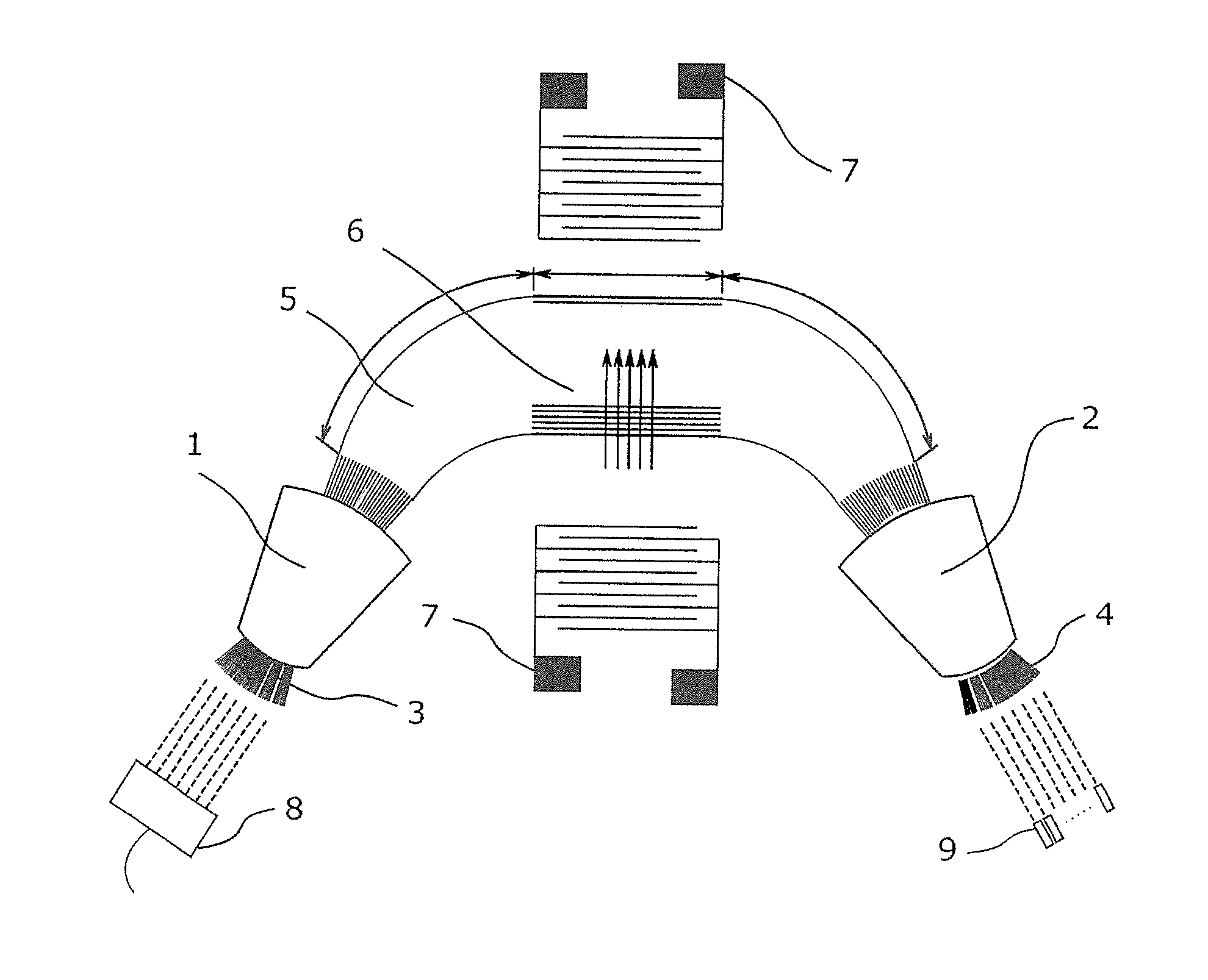
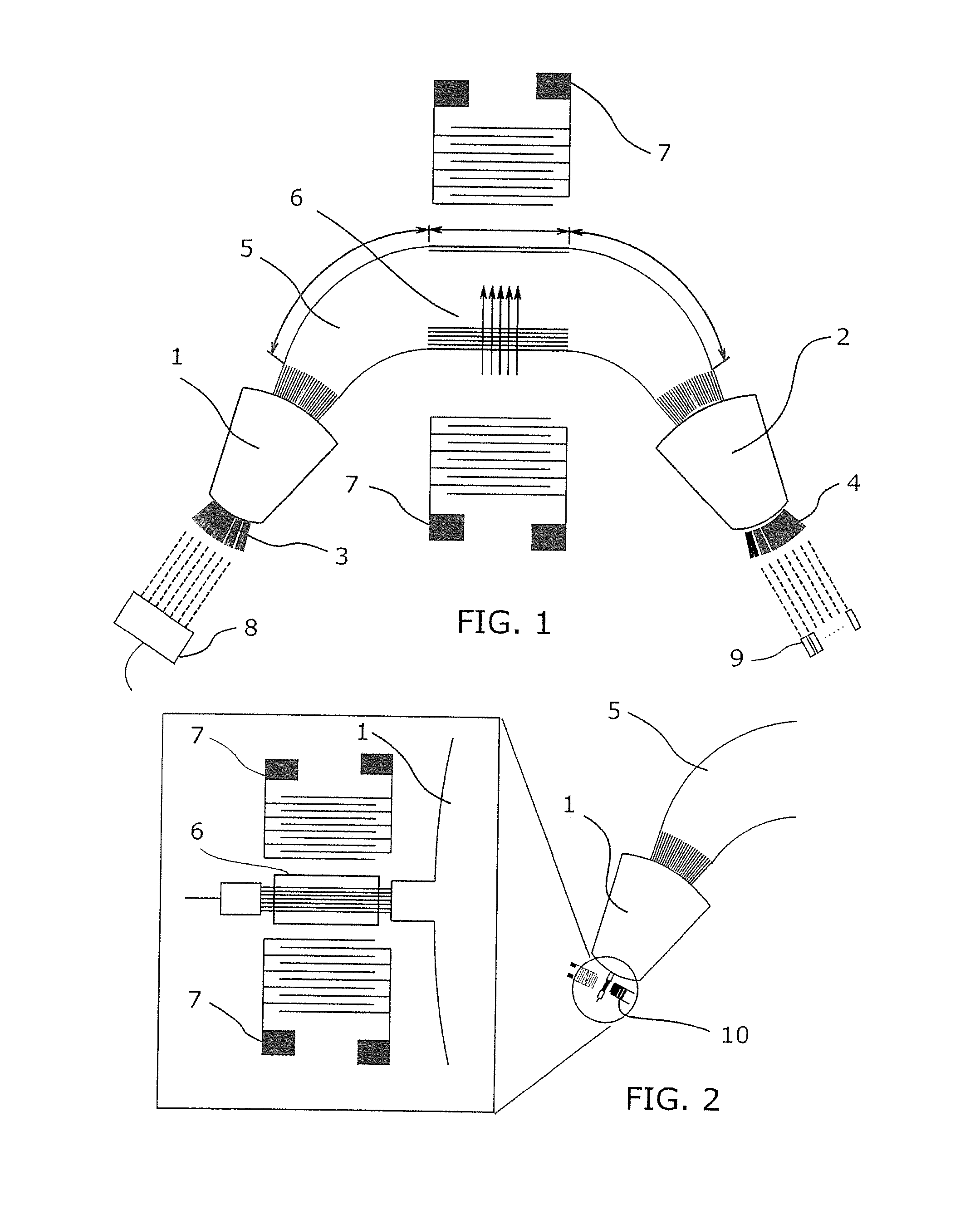
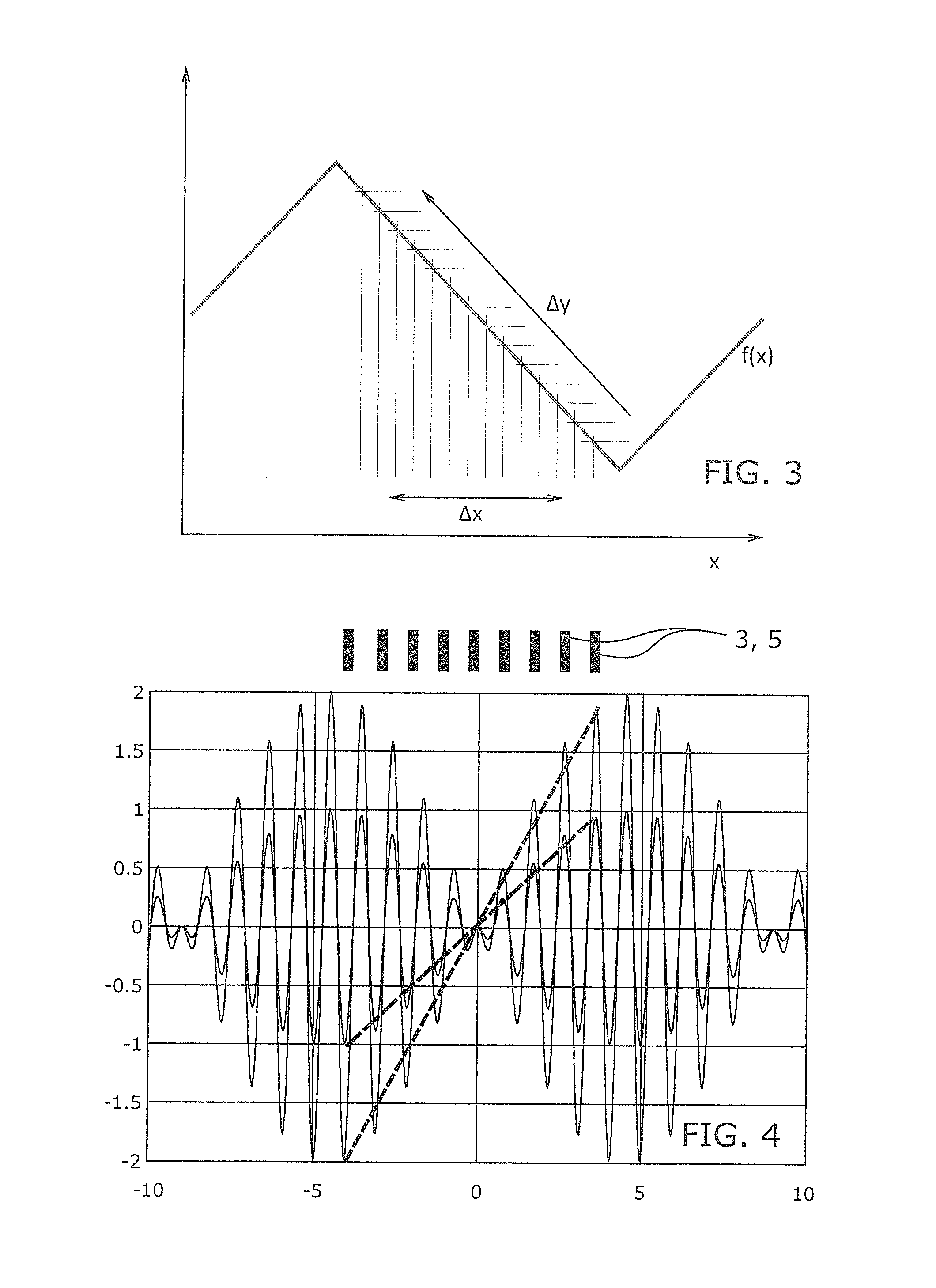
[0048]A first embodiment combines two superimposed acoustic waves with different frequencies, one multiple of the other. The sum of the two components results in a distorted wave whose overall form at the discrete points set by the optical waveguides is linearized. It is possible to use more than one mode of vibration and in particular it is possible to make use of a Fourier series expansion of a triangular function to determine the amplitudes of each of the vibration modes of the acoustic wave emitted by the transducer. The more the overlapping vibration modes, the greater is the approximation to a triangular wave with linear behaviour.

[0049]This strategy is appropriate when the acoustic wavelength is large enough such that the set of optical waveguides (i.e., the whole width of the guides) are in a section of increasing or decreasing slope of the stationary acoustic wave that excites them.

second embodiment

[0050]A second embodiment uses high frequencies, such that the acoustic wavelengths are short compared to the guide spacing. In this case at least two close frequency waves overlap, in the form sin (f0x)+sin((f0+Δf)x) with Δf the frequency difference between them. In this case the resulting wave envelope is a linearized wave at the points where the optical waveguides are found.

third embodiment

[0051]A third embodiment uses a spatial distribution of optical waveguides wherein the spacing between guides is uneven. Given a uniform sinusoidal wave expressible in the form y=sin(x) and a discretization in the variable “y”, this leads to a non-uniform distribution of the variable “x” with x=arcsin (y). Using a non-uniform distribution for waveguide separation following this strategy, that imposed by the function x=arcsin (y) wherein x is a variable discretized in accordance with a uniform grid, enables the optical guides to be excited acoustically such that the behaviour of the acoustic wave is shown (for optical waveguides) linearized. That is, if the discretized function values of this form are represented in a uniform grid, the representation of the function is linear.

[0052]An object of this invention include the particular configurations given by the dependent claims 2 to 12 which are considered included herein by reference.

[0053]Another object of this invention is an AWG de...


PUM

PropertyMeasurementUnit
lengthsaaaaaaaaaa
surface acoustic wave transmissionaaaaaaaaaa
lengthaaaaaaaaaa

Abstract

The invention relates to a tuneable AWG device for multiplexing and demultiplexing signals and to a method for tuning said device. The inventive device is an integrated-optic device which enables a signal made up of a plurality of signals multiplexed by wavelength division to be injected through an input port such as to obtain, at the output, a demultiplexed signal with each component exiting via a different port. If the multiplexed signal is changed to another input port, the demultiplexed signals appear at different ports, but always according to a pre-determined relationship. The invention makes it possible to tune the AWG device by using stationary acoustic waves such that the acoustically excited optical guides are excited by a linear acoustic wave.

Description

[0001]The present patent application is a national phase application of International Application No. PCT / ES2012 / 070335, filed May 11, 2012.OBJECT OF THE INVENTION[0002]The present invention relates to an AWG (Arrayed Waveguide Grating) device. An AWG device is an integrated optical device enabling the introduction of a signal consisting of several signals multiplexed by wavelength division through an input port so that a demultiplexed output signal is obtained with each component exiting through a different port.[0003]If the multiplexed signal is changed to another input port, the demultiplexed signals appear at different ports, but always following an established order.[0004]The present invention allows the tuning of the AWG device using acoustic stationary waves so that the optical waveguides acoustically excited are excited according to a linear acoustic wave.BACKGROUND OF THE INVENTION[0005]As defined, the AWG device is an integrated optical device that demultiplexes a composit...

Claims


Application Information

Patent Timeline
Patent Type & Authority Patents(United States)
IPC IPC(8): G02B6/12G02F1/125
CPCG02B6/12011G02B6/12016G02F1/125G02B6/12033
Inventor CAPMANY FRANCOY, JOSEMUNOZ MUNOZ, PASCUALMORAIS DE LIMA, MAURICIOSANTOS, PAULO V.
Owner UNIV POLITECNICA DE VALENCIA
Why Eureka
Try Eureka