Image reading apparatus

a technology of image reading and reading device, which is applied in the direction of instruments, digital computers, computing, etc., can solve the problems of increasing the price of image pickup devices, the low density contrast of printed images, and the cost of digital photographic printers, so as to achieve a wide dynamic range and speed up the reading operation. , to achieve the effect of improving productivity

Inactive Publication Date: 2008-03-11
FUJIFILM HLDG CORP +1
View PDF5 Cites 2 Cited by
  • Summary
  • Abstract
  • Description
  • Claims
  • Application Information

AI Technical Summary

Benefits of technology

[0019]To obtain an image with a sufficient dynamic range, it is preferable to combine plural image data obtained at plural light receiving levels with the ratio between the plural light receiving levels being about 1:16. Achieving such a ratio between plural light receiving levels by a single method, for example, by reading an image using different electric charge accumulation times is difficult. Even if it can be done, such a method increases the time required for image reading and leads to lower productivity.
[0036]The invention can provide an image reading apparatus capable of reading images with a sufficiently wide dynamic range.

Problems solved by technology

Therefore, the problem is that when image data generated by scanning an original. image using a film scanner is printed as it is, the printed image shows a low density contrast as compared with an image printed by directly exposing a photographic image recorded on a photographic film.
However, since the price of an image pickup device increases with its size, there is a demand for using smaller ones to reduce the cost of digital photographic printer.
Setting a very long electric charge accumulation time results in more time required to read an image and, eventually, lower productivity.
Also, generating an image by using image data selected from plural image data may cause shifting in color gradation, making the generated image look unnatural in its color-gradated parts.
Since the adjustability of pulse-width modulation is limited, however, it will be difficult by this method to achieve an ideal ratio (about 1:16) of light.

Method used


Image

  • Image reading apparatus
  • Image reading apparatus
  • Image reading apparatus

Examples


second embodiment

[0102]FIG. 8 is a diagram showing a scanner section of the

[0103]A scanner section 300 of the present embodiment includes an LED light source 310, a diffusion box 320, an image pickup lens 330, a half mirror 340, an ND filter 350, a CCD 361 and a CCD 362. The CCD 361 and the CCD 362 constitute an example of plural reading elements according to the invention. The light beam emitted from the LED light source 310 illuminates the half mirror 340 via the image pickup lens 330. The half mirror 340 splits the path L0 of the light beam emitted from the LED light source 310 into the path L1 leading to the CCD 361 and the path L2 leading to the CCD 362. The half mirror 340 constitutes an example of an optical path splitting section included in the image reading apparatus according to the invention.

[0104]The CPU 171 shown in FIG. 3 makes the electric charge accumulation time longer at the CCD 362 than at the CCD 361 and controls the ND filter 350 to attenuate the light beam that illuminates the...

third embodiment

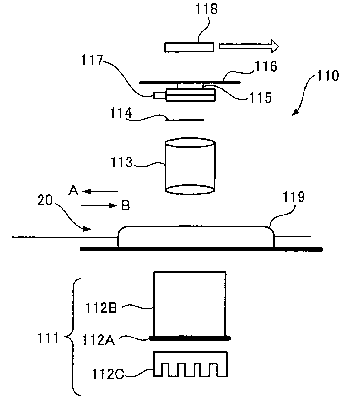
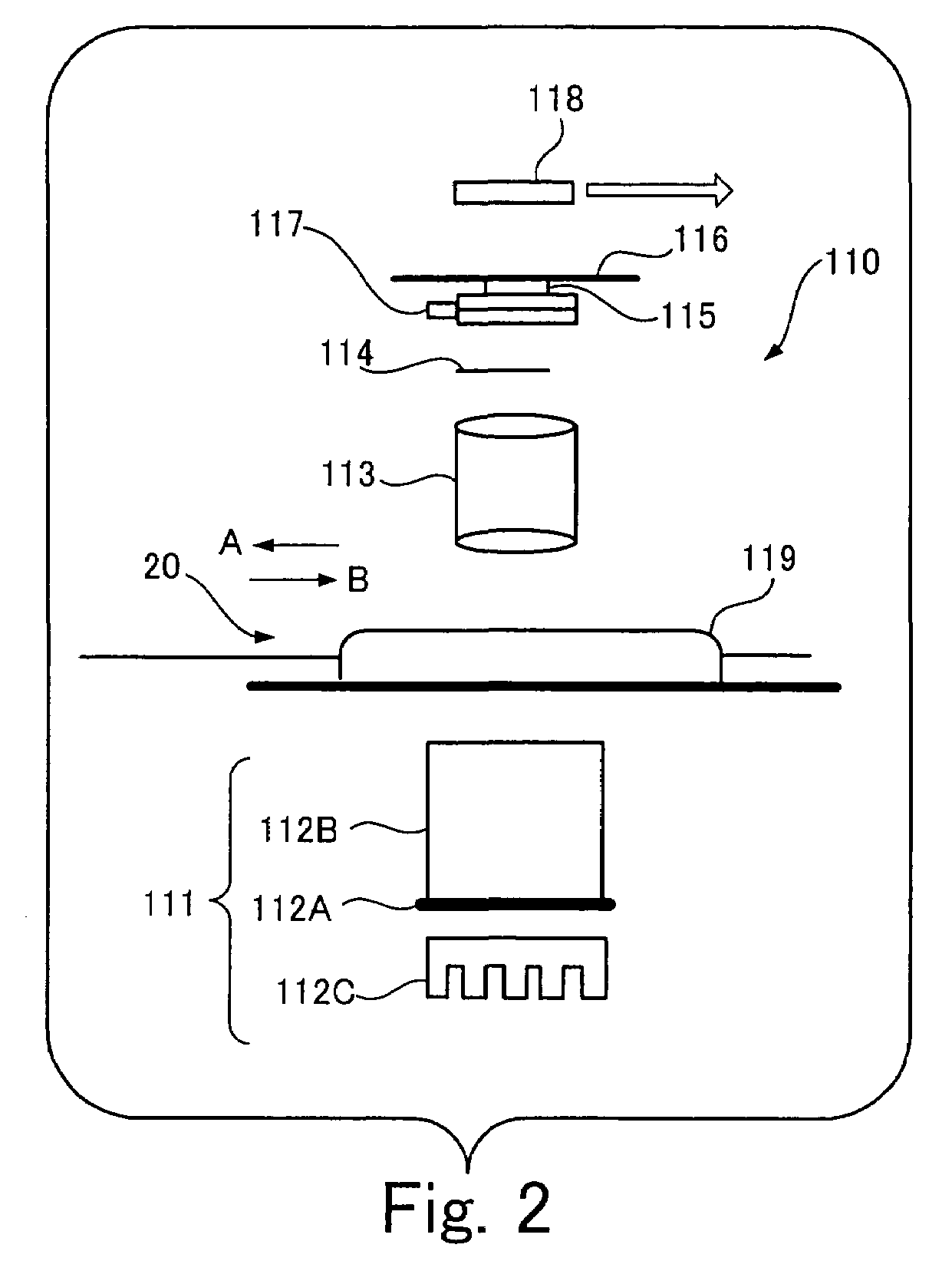
[0109]The light source 111 included in the scanner section of the third embodiment does not emit red, green and blue light beams separately. It emits white light. In this case, because white light is emitted rather than separate R, G, and B lights from the light source 111, and the color CCD (replacing the CCD 115 shown in FIG. 2) can collect the red, green and blue components included in the transmitted white light simultaneously, the processing time can be reduced. There is a drawback to the color CCD, however. That is, the image obtained using such a color CCD is inferior in quality to the image obtained using a monochrome CCD 115.

fourth embodiment

[0110]FIG. 9 is a diagram showing an example of a scanner section of a

[0111]The scanner section 400 of the fourth embodiment includes an LED light source 410, a diffusion box 420, an aperture 430, an image pickup lens 440, dichroic mirrors 450IR (“IR” representing “infrared”), 450R, 450G and 450B, line CCDs 460IR, 460R, 460G, 460B, and a film carrier 470. The LED light source 410 emits a white light beam and an infrared light beam. The light beams illuminate the dichroic mirrors 450IR, 450R, 450G and 450B after being appropriately reduced in amount by the aperture 430. The light beams reflected by the dichroic mirrors 450IR, 450R, 450G and 450B are received by the line CCDs 460IR, 460R, 460G and 460B to generate photographic image data from the respective light beams. The line CCDs 460IR, 460R, 460G and 460B are line sensors which can read an image line by line in the main scanning direction. Every time a line is scanned, the film carrier 470 moves the photographic film 20 in the su...


PUM


Abstract

The present invention provides an image reading apparatus capable of reading images with a sufficiently wide dynamic range. An image reading apparatus of this invention has a light source, a reading section which generates image data based on light obtained from an original illuminated with light from the light source, a first level changing section which changes a light receiving level in the reading section in a first manner, a second level changing section which changes the light receiving level in a second manner different from the first manner, a control section in which plural light receiving levels are generated by synergistically changing a light receiving level, and a combining section which combines plural image data obtained by reading an image of an original at plural light receiving levels.

Description

BACKGROUND OF THE INVENTION[0001]1. Field of the Invention[0002]The present invention relates to an image reading apparatus which reads original images and generates image data representing the original images.[0003]2. Description of the Related Art[0004]Image reading apparatuses which read an original image by illuminating it with light and collecting the light reflected from or transmitted through it have conventionally been in wide use. A photographic digital printer to print out images recorded on a photographic film, for example, has a film scanner which reads images recorded on a photographic film by receiving light applied to and transmitted through the photographic film using image pickup devices such as CCDs. The resultant images read by the film scanner are sent to a printer incorporated in the photographic digital printer and then printed out.[0005]Generally, the range of density (hereafter referred to as a dynamic range) that can be read by an image pickup device is narr...

Claims


Application Information

Patent Timeline
Patent Type & Authority Patents(United States)
IPC IPC(8): G06F15/00H04N1/387G06T1/00G06T3/00H04N1/00H04N1/028H04N1/04H04N1/19H04N1/40H04N1/48
CPCH04N1/02815H04N1/02895H04N1/40056H04N1/48
Inventor NAKAMURA, YOICHI
Owner FUJIFILM HLDG CORP
Why Eureka
Try Eureka