Supercharge Your Innovation With Domain-Expert AI Agents!

Accurate current sensing in H-bridge applications without amplifier having high common mode rejection ratio

a technology of h-bridge and current sensing, which is applied in the direction of power supply testing, instruments, process and machine control, etc., can solve the problems of difficult trade-offs between optimizing for dc accuracy and dc error measurements, and the information provided by this approach may not be as accurate as the direct measurement of current to the motor winding

Active Publication Date: 2016-01-19
ANALOG DEVICES INT UNLTD
View PDF20 Cites 2 Cited by
  • Summary
  • Abstract
  • Description
  • Claims
  • Application Information

AI Technical Summary

Benefits of technology

The patent describes a current sensing circuit that uses a shunt resistance to measure current. The circuit has two differential amplifiers that provide amplified signals across the shunt resistance. One amplifier has a low output DC offset voltage when the common mode voltage is low, while the other amplifier has a high output DC offset voltage when the common mode voltage is high. This allows the circuit to accurately measure current controlled by switches that switch at a high frequency. The circuit has a low common mode voltage rejection ratio, which means it can measure current accurately even when there is a lot of electromagnetic interference in the environment. This results in a higher accuracy and reliability of the current measurements.

Problems solved by technology

This may cause errors in the measurements made by the differential amplifier.
However, difficult trade-offs between optimizing for DC accuracy (offset voltage) and AC performance (AC CMRR) may be needed.
Some H-bridge driven motor controllers may not directly measure the current in the motor winding.
However, the information provided by this approach may not be as accurate as directly measuring the current to the motor winding.

Method used


Image

  • Accurate current sensing in H-bridge applications without amplifier having high common mode rejection ratio
  • Accurate current sensing in H-bridge applications without amplifier having high common mode rejection ratio
  • Accurate current sensing in H-bridge applications without amplifier having high common mode rejection ratio

Examples


Embodiment Construction

[0020]Illustrative embodiments are now described. Other embodiments may be used in addition or instead. Details that may be apparent or unnecessary may be omitted to save space or for a more effective presentation. Some embodiments may be practiced with additional components or steps and / or without all of the components or steps that are described.

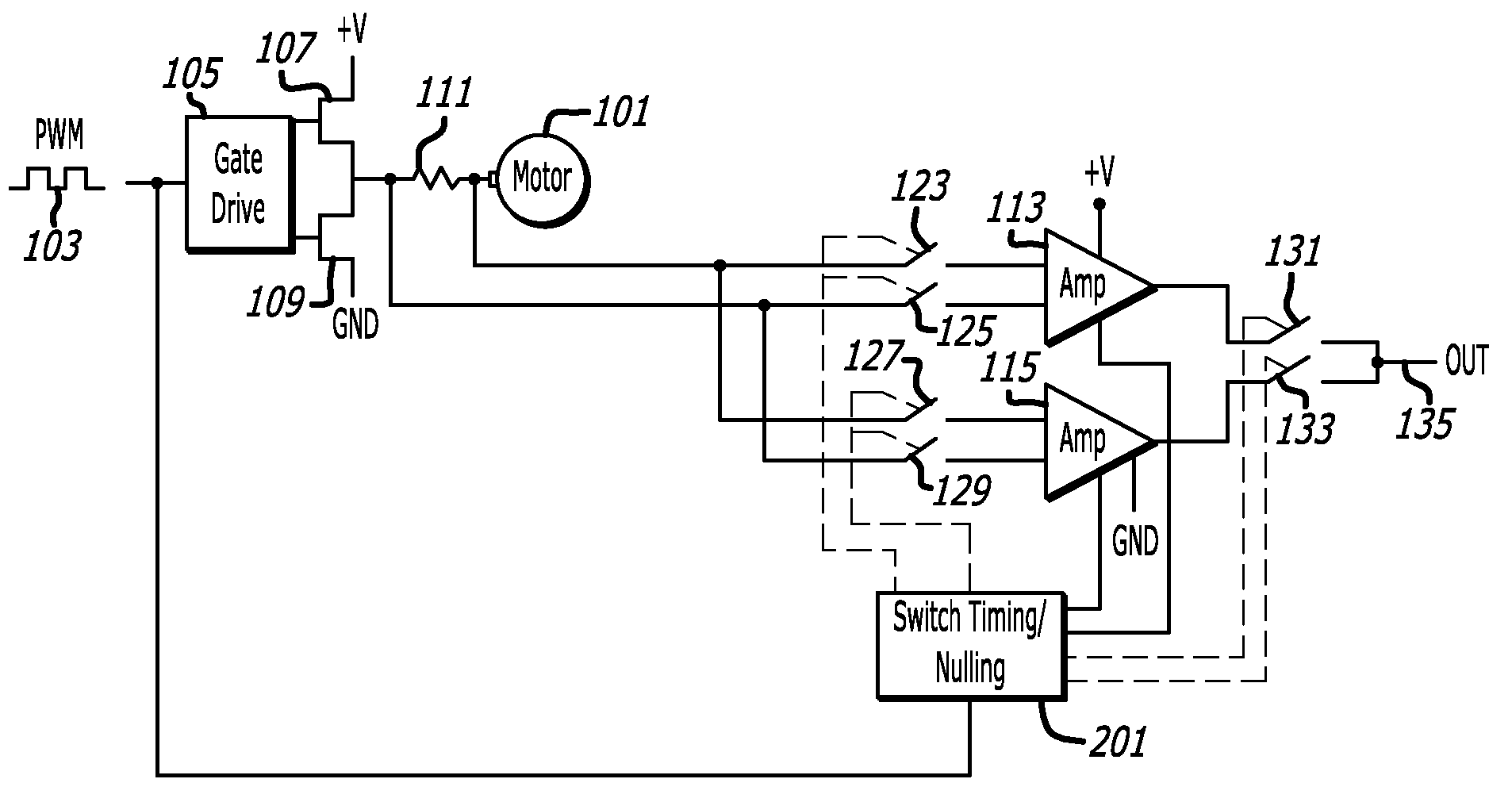
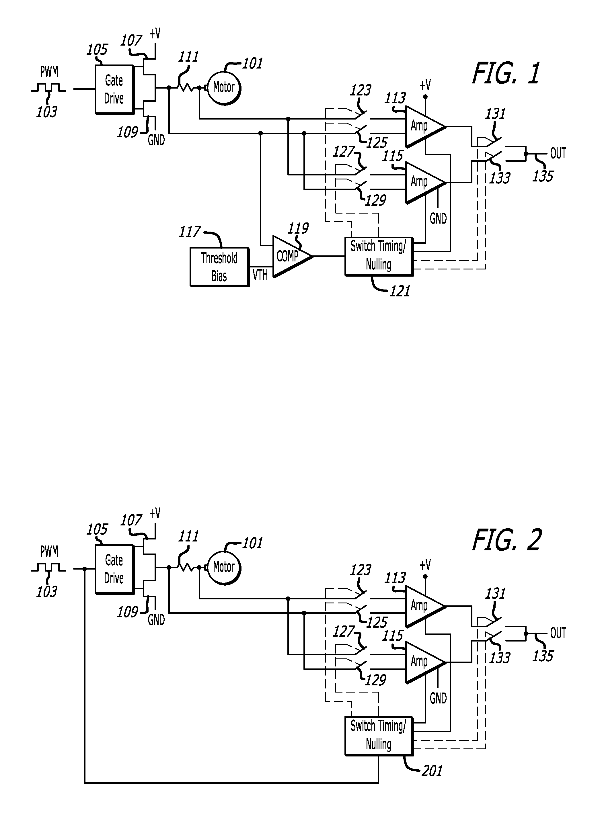
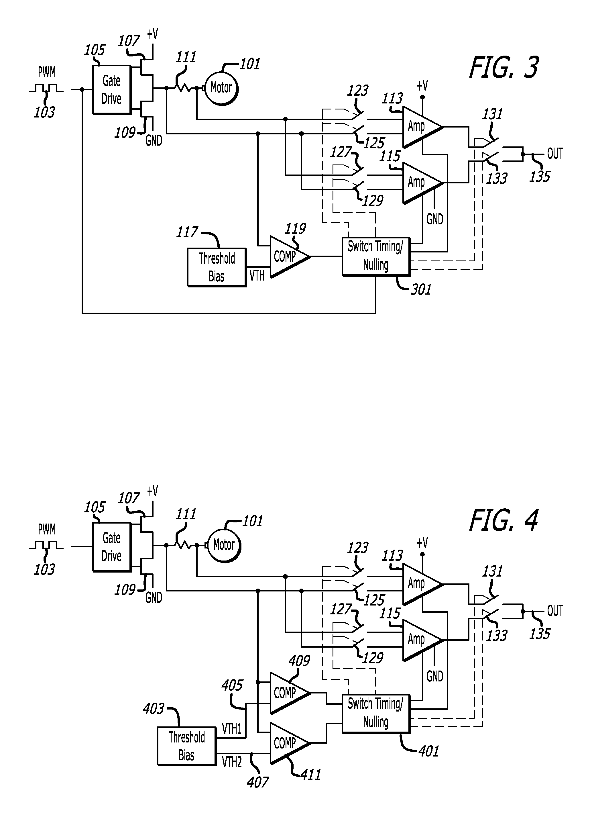
[0021]FIG. 1 is an example of a motor 101 and a circuit for driving a winding of the motor 101 that may include a pulse-width-modulated (PWM) drive signal 103, a gate drive circuit 105, H-bridge switches 107 and 109, and a current sensing circuit. The current sensing circuit accurately measures current to the motor 101 and may include a shunt resistance 111, differential amplifiers 113 and 115, and a switching system that includes a threshold bias circuit 117, a comparator 119, a switch timing / nulling circuit 121, and electronic switches 123, 125, 127, 129, 131, and 133.

[0022]The motor 101 may be of any type. For example, the motor may be ...


PUM


Abstract

A current sensing circuit may include a shunt resistance through which current to be sensed travels. A first and a second differential amplifier may each provide an amplified output of the voltage across the shunt resistance. A switching system may deliver a current sensing signal output based on the amplified output of the first differential amplifier when the common mode voltage across the shunt resistance is low and based on the amplified output of the second differential amplifier when the common mode voltage across the shunt resistance is high. The first differential amplifier may provide its lowest output DC offset voltage when the common mode voltage is low, while the second differential amplifier may provide its lowest output DC offset voltage when the common mode voltage is high. The first and second differential amplifiers may both have a low common mode voltage rejection ratio, such as a ratio of less than 40 db at the switching frequency of switches that control the current that is sensed.

Description

CROSS-REFERENCE TO RELATED APPLICATION[0001]This application is based upon and claims priority to U.S. provisional patent application 61 / 866,334, entitled “Current Sensing for H-Bridge Applications,” filed Aug. 15, 2013. The entire content of this application is incorporated herein by reference.BACKGROUND[0002]1. Technical Field[0003]This disclosure relates to current sensing circuits, including current sensing circuits that control motors driven by an H-bridge of electronic switches.[0004]2. Description of Related Art[0005]The windings of a motor may each be driven by an H-bridge of electronic switches, which may be driven by a pulse-width-modulated (PWM) signal.[0006]The system may need to continually measure the current flowing into (or out of) each motor winding. To effectuate this needed measurement, a shunt resistance may be placed in series with each winding, and the differential voltage across each shunt resistance may be measured and serve as an indication of the current th...

Claims


Application Information

Patent Timeline
Patent Type & Authority Patents(United States)
IPC IPC(8): H02P7/18G01R19/00H02P31/00H02M3/158G01R19/165G01R1/20G01R31/40
CPCH02M3/158H02P31/00G01R19/0092G01R31/40G01R1/203G01R19/16538
Inventor LOKERE, KRISTIAAN B.WHELAN, BRENDAN J.
Owner ANALOG DEVICES INT UNLTD
Features
  • R&D
  • Intellectual Property
  • Life Sciences
  • Materials
  • Tech Scout
  • Unparalleled Data Quality
  • Higher Quality Content
  • 60% Fewer Hallucinations
Learn More