Sports garments with enhanced visual and/or moisture management properties

a technology of visual and/or moisture management and sportswear, applied in the field of sportswear, can solve problems such as flickering effect while the wearer is running, and achieve the effect of enhancing visibility

Active Publication Date: 2016-01-26
NIKE INC
View PDF30 Cites 5 Cited by
  • Summary
  • Abstract
  • Description
  • Claims
  • Application Information

AI Technical Summary

Benefits of technology

[0005]The present application describes garments that may be used as part of a sports uniform that can provide enhanced visibility for members of a team viewing the athlete wearing the uniform. The present application further describes a garment that may provide advantageous moisture management characteristics to move perspiration from the skin of an athlete to the outer layer of the garment to permit evaporation using a denier differential mechanism.
[0006]Garments or uniforms in accordance with the present invention may improve the perception of the location and movement of teammates during competition, and hence improve the coordinated quality of play, by providing one or more enhanced visual properties. For example, visibility zones on a garment or a uniform comprising multiple garments may visually contrast with other regions of the garment or uniform and / or the visual background experienced by teammates during competition. Visual contrast may be created using luminance contrasts and / or color contrasts. For example, color contrasts selected using a color definition such as the CIE (1931) Standard Chromaticity Diagram to permit both normally sighted and color deficient individuals to equally perceive the color contrast of the garment. Visibility to teammates may be further enhanced by creating a spectral window corresponding with the visual background in which all or part of a garment or uniform is substantially non-reflective. Visibility to teammates may also be enhanced by locating visibility zones on a garment or uniform at locations that, when the uniform is worn during competition, correspond to lines of sight of teammates. Further, visibility zones may be located at or near the wearer's joints or “hinge points” when the uniform or garment is worn during competition to provide greater information regarding the location, orientation, speed, and / or acceleration of the wearer to teammates. Visibility zones may alternatively or additionally outline all or part of the lateral portions of a wearer's body to make the wearer more readily visible to teammates and to assist teammates in evaluating the orientation and movement of the wearer during play.
[0007]Garments or uniforms in accordance with the present invention may also improve the perception of the location and movements of teammates during competition by creating visual change perceivable by teammates. For example, a varying pattern on a garment or uniform may enhance the visibility of the wearer to teammates, particularly in the peripheral vision of teammates. Another way to create visual change in garments or uniforms in accordance with the present invention may use “flicker” to enhance the visibility of a wearer to teammates. Flicker occurs when a visually property changes rapidly. Flicker may be created in garments or uniforms in accordance with the present invention in various ways. For example, a garment or uniform may have flicker zones on the inside of a wearer's legs, causing a flicker effect while the wearer runs. Flicker zones may similarly be located on the sides (where they will be intermittently obscured by the wearer's arms), on the inside portion of a shoe, or at other locations as appropriate for the sport in question and the particular type of garment. By way of further example, the shape, texture, and / or contour of the surface of a garment or uniform may cause various zones with contrasting visual properties to come in or out of view to a teammate when the wearer moves. For example, molded portions of materials such as thermal plastics, adhesives, etc., may be used to form flicker zones. Further, heat transfers, decals, patches, or other materials may be affixed to a garment to create a flicker zone. As yet another example, aerographic techniques may be used to remove fibers to reveal other fibers to create a flicker zone. By way of yet further example, garments or uniforms in accordance with the present invention may comprise multiple contrasting layers, with the outer layer providing openings through which an inner layer may be viewed, either continuously or intermittently, as the wearer moves and the outward facing layer stretches or moves. By selecting yarns with contrasting luminance and / or color positions on the CIE (1931) Standard Chromaticity Diagram to create one or multiple layers of a garment, a visual contrast may be created between the skin facing layer and the outward facing layer that facilitates perception of the position and motion of a wearer by his or her teammates. Holes or windows permitting viewing of an inner layer may be positioned on a garment selectively such that viewing angles common for teammates may coincide with the contrasting zones created, while optionally minimizing the view obtained by opponents.
[0008]Further, garments or uniforms in accordance with the present invention may be formed from multiple layers with dernier per filament values selected so as to create a denier differential across the layers of a garment to facilitate the movement of moisture from the skin of an athlete to the surface of the garment for evaporation. Openings in layers of a garment may also be located to enhance the cooling of the wearer.

Problems solved by technology

For example, a garment or uniform may have flicker zones on the inside of a wearer's legs, causing a flicker effect while the wearer runs.

Method used


Image

  • Sports garments with enhanced visual and/or moisture management properties
  • Sports garments with enhanced visual and/or moisture management properties
  • Sports garments with enhanced visual and/or moisture management properties

Examples


Embodiment Construction

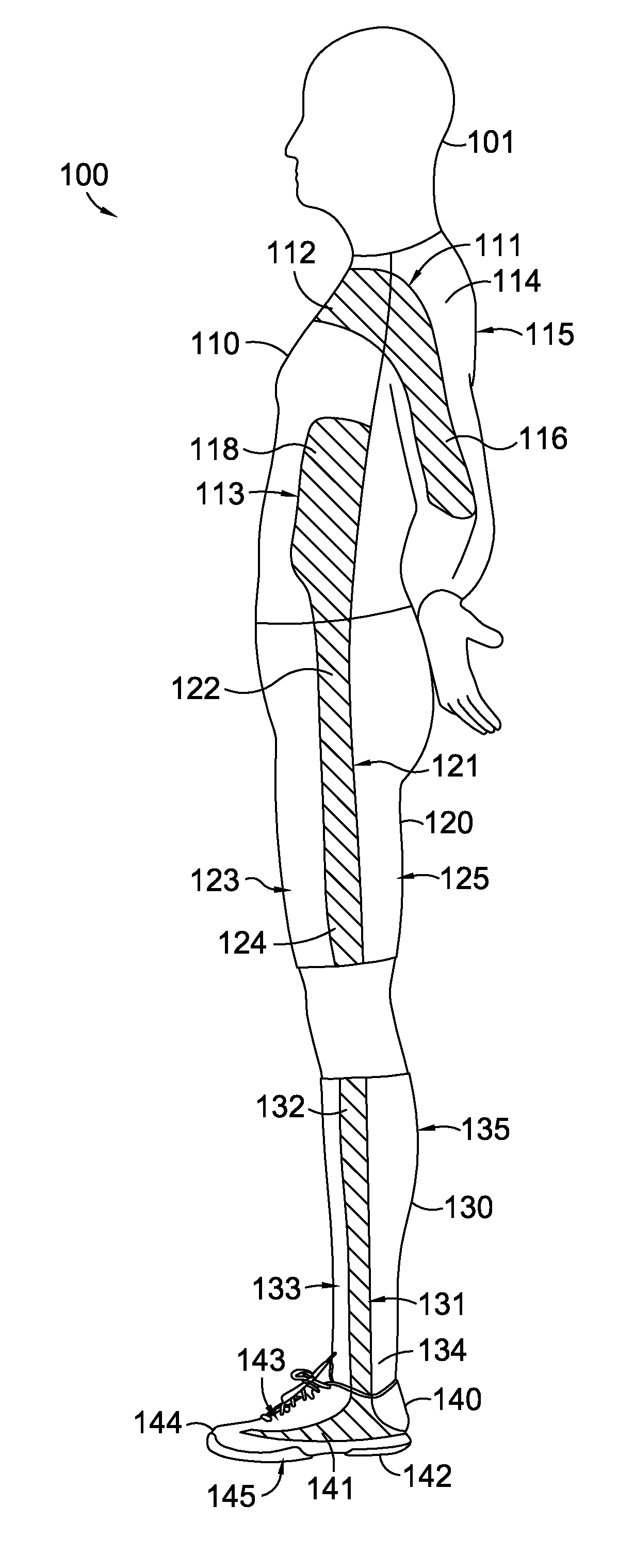
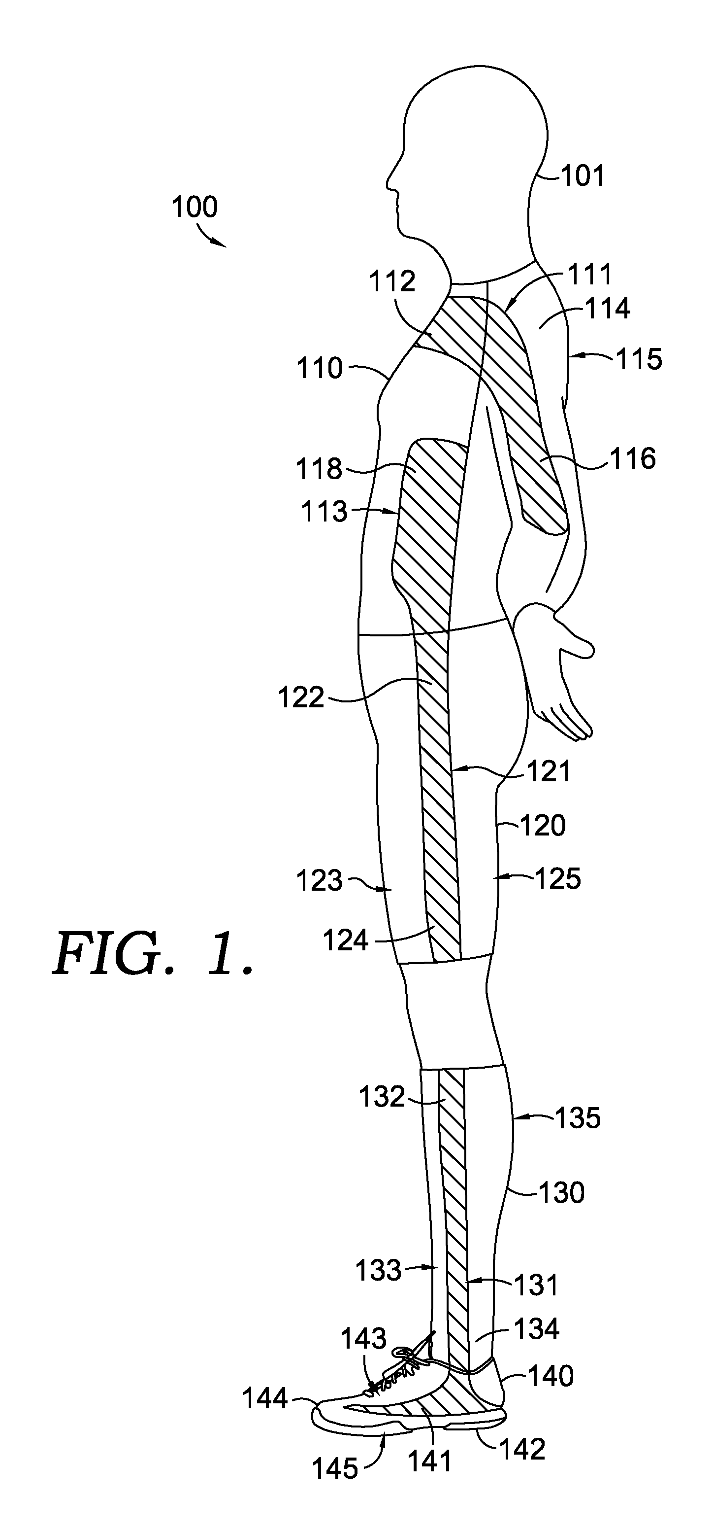
[0032]A garment in accordance with the present invention may be a garment, a sports uniform or any sports uniform component. The term “garment” is used herein to refer to anything worn during athletic competition, such as jerseys, shirts, shorts, pants, socks, shoes, safety equipment, sweat bands, etc.

[0033]A garment in accordance with the present invention may advantageously create visual contrast to facilitate recognition of the wearer by his or her teammates or others during competition or training. The visual contrast created by a garment in accordance with the present invention may be between different zones on the garment itself and / or between the garment and the visual background experienced by teammates of the wearer during athletic competition. Visibility zones may be located on a garment or uniform to be particularly visible to teammates and / or to provide particularly useful information to teammates. The visual properties that create contrast for a garment created in accor...


PUM


Abstract

A garment, such as a sports uniform, may provide visibility zones and / or flicker zones to enhance the ability of teammates to perceive the wearer. Different zones on a garment may have different sets of visual properties that may contrast with one another and / or a visual background. A denier differential between layers of a garment may facilitate moisture transport across the layers of the garment. Flicker zones may be discrete from or combined with visibility zones. One or more zones of a garment may also be substantially non-reflective at wavelengths associated with the visual background encountered while wearing the garment.

Description

CROSS-REFERENCE TO RELATED APPLICATIONS[0001]This application claims priority to provisional patent application No. 61 / 448,908, filed Mar. 3, 2011, entitled Double Layered Garment With Enhanced Visual and / or Moisture Management Properties.STATEMENT REGARDING FEDERALLY SPONSORED RESEARCH OR DEVELOPMENT[0002]Not applicable.TECHNICAL FIELD[0003]The present application relates to garments and, more particularly, sporting uniforms. The present application further relates to garments that enhance the perception of teammates during competition to improve coordinated athletic competition.BACKGROUND OF THE INVENTION[0004]Both the comfort and visual properties of sporting uniforms can be important to performance. Team sports such as soccer require a teammate to visually perceive and identify his or her teammates during play in order to complete passes, coordinate defense, and the like. Enhancing the visual perception of a teammate has traditionally been accomplished by using different colors ...

Claims


Application Information

Patent Timeline
Patent Type & Authority Patents(United States)
IPC IPC(8): A41D1/00A41D13/00A63B71/06
CPCA41D13/0015A63B71/0622A63B2243/0066A41D2400/20A63B2071/0661A63B2071/0694A63B2243/007A63B2243/0025A63B2243/0037A41D31/02A63B2102/14A63B2102/18A63B2102/22A63B2102/24A41D31/14A41D27/08A41D31/125A41D13/01
Inventor SOKOLOWSKI, SUSAN L.MAYER, KIRK M.MORGAN, AMIR H.REICHOW, ALAN W.STAUB, ANDREA J.SCOTT, STEPHANIE J.
Owner NIKE INC
Why Eureka
Try Eureka