
Method for the cylindrical grinding of a workpiece, system containing the workpiece and apparatus for the centreless grinding of the system

a one-piece workpiece and cylindrical grinding technology, which is applied in the direction of grinding/polishing apparatus, grinding machine components, grinding machines, etc., can solve the problem of narrow range of unbalance of individual balancer shafts, and achieve high accuracy

Active Publication Date: 2016-01-26
ERWIN JUNKER GRINDING TECH
View PDF8 Cites 0 Cited by
  • Summary
  • Abstract
  • Description
  • Claims
  • Application Information

AI Technical Summary

Benefits of technology

[0008]It is therefore the underlying object of the invention to provide a method for cylindrical grinding by means of which the cylindrical and rotationally symmetrical first longitudinal region of said “unbalanced” workpieces can be ground with high accuracy in a manner suitable for economical mass production.
[0010]The method according to the invention has the advantage that the conventional and known machines for centerless cylindrical grinding can be used, cf. in this connection, for example, Dubbel, Taschenbuch für den Maschinenbau [Mechanical Engineering Handbook], 18th edition, pages T89 / T90. In the present case, centerless cylindrical grinding is also of advantage because, for example, the balancer shafts mentioned can be produced in large numbers and are already in the form of forged or cast blanks and of very uniform quality after machining. Hence, the unbalance of the individual balancer shafts is therefore also within a relatively narrow range. It is thus possible with just a single type of balancing weight to achieve an economical process which allows a high degree of automation.
[0011]If the individual workpieces differ to a relatively great extent from one another, it is also possible to measure the residual unbalance thereof before grinding and to mount different balancing masses on the workpieces depending on requirements. In this way, the quality of the grinding process can be optimized even further. In general, the balancing masses are attached releasably to the workpieces. However, they do not have to be removed again immediately on completion of cylindrical grinding but can also be of advantage for additional production processes. For example, an appropriately dimensioned and shaped balancing mass can also be used as a grip for an automatic production linkage device or an assembly process. Moreover, the balancing mass may be useful for stabilizing the workpiece in additional transfer and processing operations.
[0018]If two or more rotationally symmetrical first longitudinal portions are to be ground on the workpiece to be ground, grinding can be performed with a centerless cylindrical grinding machine which has a dedicated grinding set for each individual longitudinal portion, said set comprising a regulating wheel, a grinding wheel and a support rail. In this way, all the first longitudinal portions can be ground simultaneously.
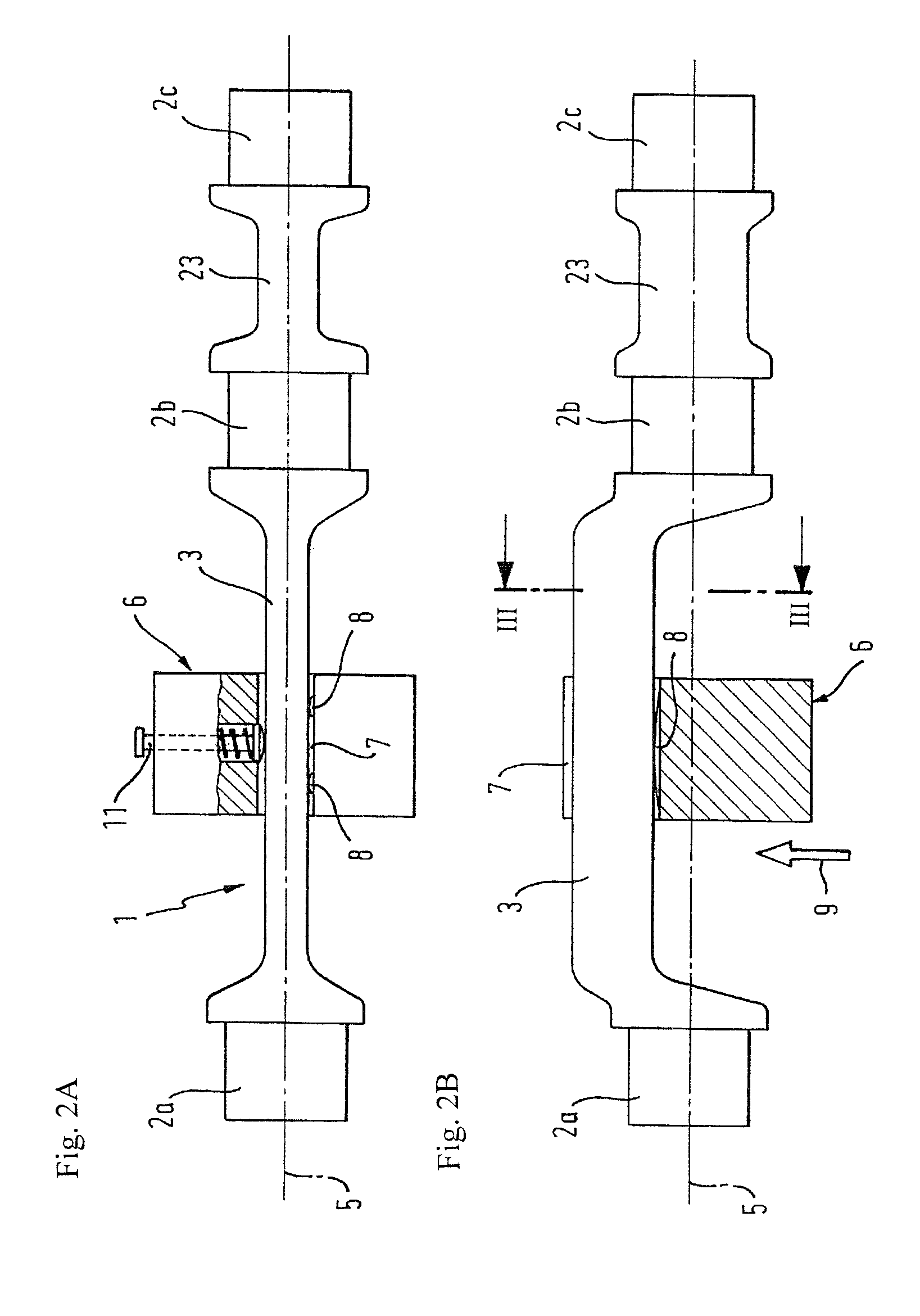
[0021]It is furthermore an advantageous characteristic of the system if the workpiece and the balancing body are assembled by means of a recess extending radially in the balancing body, wherein the balancing body is mounted by means of the recess on an eccentrically arranged longitudinal web of the workpiece.
[0023]In simple cases and at low production numbers, the balancing weight will be mounted individually and by had on the workpiece. If, however, the preconditions for mass production are met, it makes more sense for the assembly and, if appropriate, disassembly of the system to be performed automatically within the apparatus or in direct functional association therewith. In this way, a combined processing station can be effected, to which the workpieces are brought in a preprocessed state on a conveyor belt and are transferred from the conveyor belt into an assembly station and, from there, transferred again to the machine for centerless cylindrical grinding by loading gantries. The fully ground workpieces are also transferred back to the conveyor belt by loading gantries, and a station for removal of the balancing weights may also be provided, if appropriate.

Problems solved by technology

Hence, the unbalance of the individual balancer shafts is therefore also within a relatively narrow range.

Method used


Image

  • Method for the cylindrical grinding of a workpiece, system containing the workpiece and apparatus for the centreless grinding of the system
  • Method for the cylindrical grinding of a workpiece, system containing the workpiece and apparatus for the centreless grinding of the system
  • Method for the cylindrical grinding of a workpiece, system containing the workpiece and apparatus for the centreless grinding of the system

Examples


Embodiment Construction

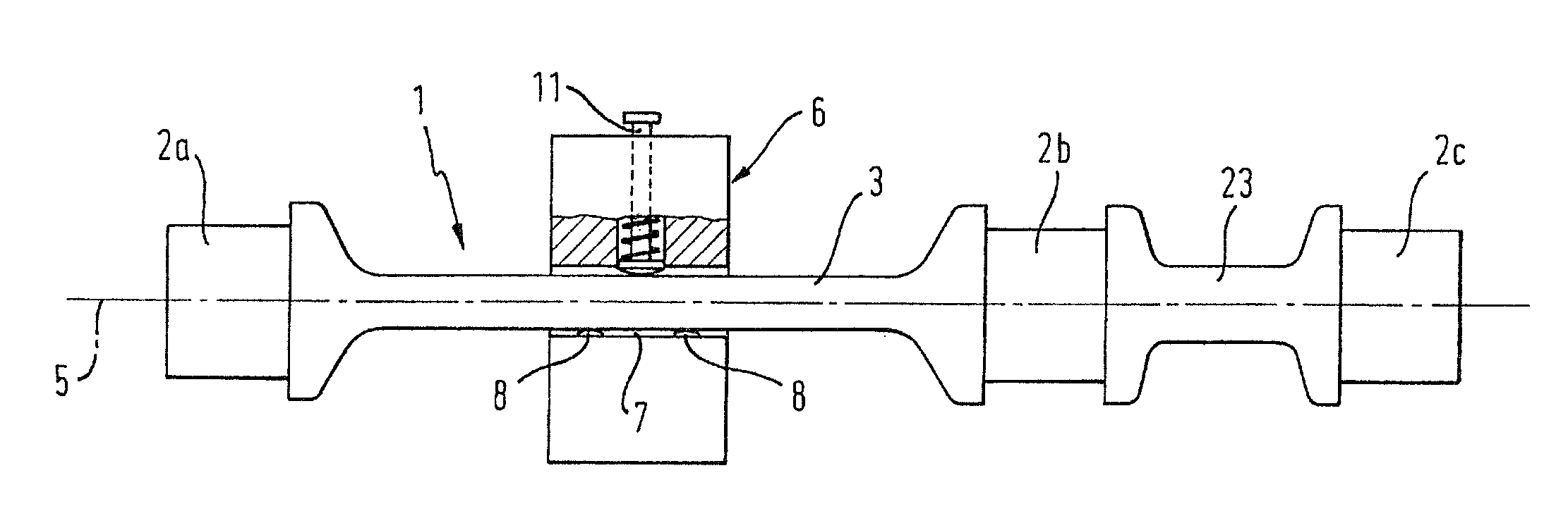
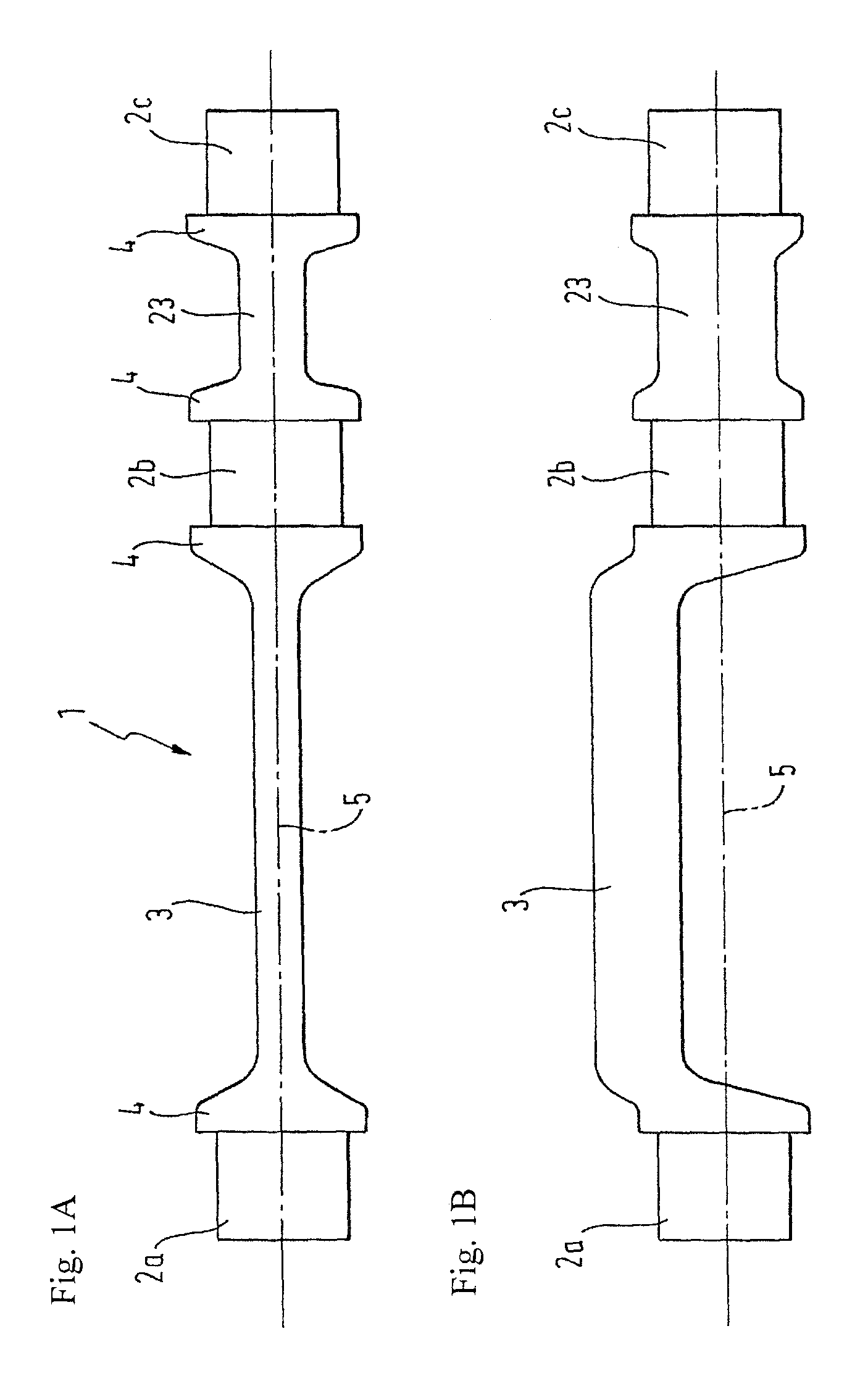
[0032]FIGS. 1A and 1B show two views of a balancer shaft of the kind increasingly being used on modern internal combustion engines. This balancer shaft is a good example of a workpiece 1 which can advantageously be ground by the method according to the invention. The workpiece 1 has a continuous longitudinal axis 5, by which the contour of the workpiece 1 is defined. In comparison with FIG. 1A, FIG. 1B has been rotated by 90° about the longitudinal axis 5. As can be seen from comparing FIGS. 1A and 1B, the workpiece 1 has first longitudinal portions 2a, 2b, 2c, which are cylindrical with respect to the continuous longitudinal axis 5 and can subsequently serve as bearing locations. Between the rotationally symmetrical first longitudinal portions 2a and 2b there is a second longitudinal portion 3, which departs from a rotationally symmetrical contour in cross section. Here, the second longitudinal portion 3 has an eccentric contour in the form of a flat longitudinal web, which in this...


PUM

PropertyMeasurementUnit
massaaaaaaaaaa
radial distanceaaaaaaaaaa
pressureaaaaaaaaaa

Abstract

On a workpiece there are first longitudinal portions which are rotationally symmetrical with respect to the continuous longitudinal axis and are intended to be ground by way of centerless grinding. The workpiece also has a second longitudinal portion, which is not rotationally symmetrical with respect to the longitudinal axis and would lead to imbalance in the event of rotation. Therefore, a balancing weight having a radially extending recess is placed on the second longitudinal portion. The balancing weight contributes largely to uniform distribution of the rotating masses, thus reduces the imbalance to a very low residual imbalance and allows reliable and precise centerless grinding.

Description

BACKGROUND OF THE INVENTION[0001]The invention relates to a method for the cylindrical grinding of a one-piece workpiece, the contour of which is defined by a continuous longitudinal axis and, in addition to a first longitudinal region, which is cylindrical with respect to said longitudinal axis, also has a second longitudinal region, in which the radial distribution of mass in relation to the longitudinal axis is non-uniform.[0002]Workpieces of this kind are known. They are contoured in accordance with a continuous longitudinal axis, this longitudinal axis simultaneously being a center line and an axis of rotation during subsequent operation. However, only some of them have one or more longitudinal portions of cylindrical cross section which are rotationally symmetrical in relation to the longitudinal axis. In another longitudinal region, the radial distribution of mass is non-uniform because the radial circumferential contour is eccentric or not rotationally symmetrical in some ot...

Claims


Application Information

Patent Timeline
Patent Type & Authority Patents(United States)
IPC IPC(8): B24B5/35B24B5/00B24B41/00B24B5/42B24B1/00B24B5/22
CPCB24B5/00B24B1/00B24B5/22B24B5/35B24B5/428B24B41/007B24B5/42B24B41/06
Inventor JUNKER, ERWINMUELLER, HUBERT
Owner ERWIN JUNKER GRINDING TECH
Learn More