Self-aligning modular latch

a self-aligning, modular technology, applied in the direction of carpet fasteners, lock applications, instruments, etc., can solve the problems of limited stroke, memory alloy wire actuators, and increased parts cos

Active Publication Date: 2016-01-26
CAREFUSION 303 INC
View PDF87 Cites 21 Cited by
  • Summary
  • Abstract
  • Description
  • Claims
  • Application Information

AI Technical Summary

Benefits of technology

[0005]Secure lidded containers may incorporate lid-release actuators that use memory alloy wire to release the lid. One drawback of memory alloy wire actuators is that they have a limited stroke, and therefore require that the latching elements be precisely located with respect to each other to reliably engage and disengage. Achieving this precise relative alignment may require the use of tighter tolerances than normally used in plastic parts, increasing the cost of the parts. Another approach incorporates an adjustable feature into the container, which typically adds cost to the parts as well as requiring additional labor to make the adjustment during assembly. It would be advantageous to be able to precisely locate the mating elements of a memory alloy wire actuated latch while allowing the use of standard tolerances for the components.

Problems solved by technology

One drawback of memory alloy wire actuators is that they have a limited stroke, and therefore require that the latching elements be precisely located with respect to each other to reliably engage and disengage.
Achieving this precise relative alignment may require the use of tighter tolerances than normally used in plastic parts, increasing the cost of the parts.
Another approach incorporates an adjustable feature into the container, which typically adds cost to the parts as well as requiring additional labor to make the adjustment during assembly.

Method used


Image

  • Self-aligning modular latch
  • Self-aligning modular latch
  • Self-aligning modular latch

Examples


Embodiment Construction

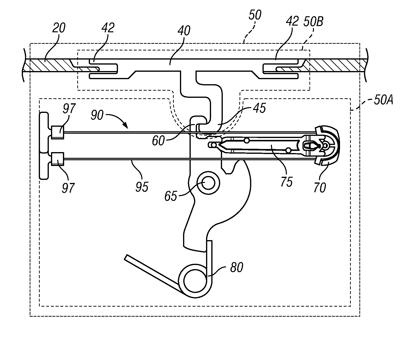
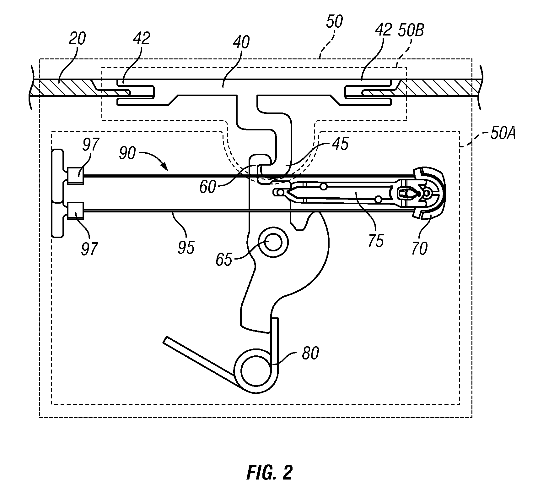
[0017]The following description discloses embodiments of a container having a self-aligning latch such that tolerances in the assembly of the lidded container are compensated for by lateral motion of the latch fastener with respect to the engagement mechanism. These features allow the use of wider tolerances in the fabrication and assembly of the parts of the lidded container while still enabling the use of a lid-release actuator having a limited stroke.

[0018]In the following detailed description, numerous specific details are set forth to provide a full understanding of the present disclosure. It will be apparent, however, to one ordinarily skilled in the art that embodiments of the present disclosure may be practiced without some of the specific details. In other instances, well-known structures and techniques have not been shown in detail so as not to obscure the disclosure.

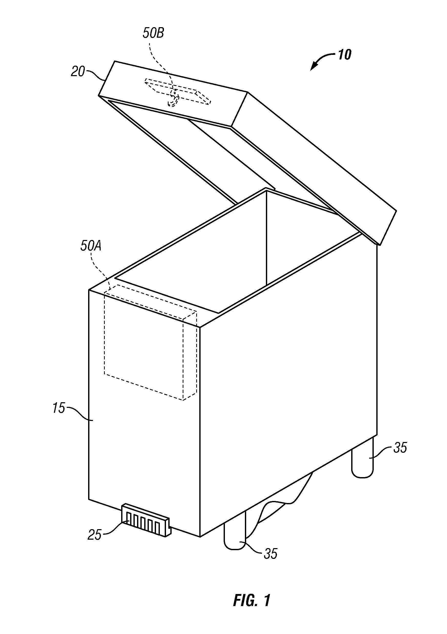
[0019]The method and system disclosed herein are presented in terms of a container adapted to contain medic...


PUM


Abstract

A container is disclosed that has a housing and a lid. The lid has a planar portion and a latch that is freely movable parallel to the planar portion of the lid. The latch has a retention feature and a first reference surface that is perpendicular to the planar portion of the lid. There is a latch mechanism coupled to the housing that has an engagement element configured to engage the retention feature of the latch and a first alignment feature having a first alignment surface. The first alignment feature is configured to laterally displace the latch in a first direction such that the first reference surface aligns with the first alignment surface when the lid is brought together with the housing with the fastener laterally displaced away from the engagement element in a second direction that is opposite to the first direction.

Description

BACKGROUND[0001]1. Field[0002]The present disclosure generally relates to systems and methods of providing secure storage and, in particular, relates to mechanisms that guide latch elements into precise alignment to compensate for tolerances in components and clearances in the assembly.[0003]2. Description of the Related Art[0004]Hospitals have a need to provide secure storage for certain medications such as narcotics and controlled substances while still making the medications available to care givers. One method of accomplishing this is to use lidded containers where the lid can only be opened when the container is connected to a power source and processor that can send the appropriate digital commands. The lidded container is filled with a medication in the pharmacy and the lid closed. While the container is being transported to the local Automatic Dispensing Machine (ADM), the contents of the container are secure as the lid cannot be opened without breaking the container. The co...

Claims


Application Information

Patent Timeline
Patent Type & Authority Patents(United States)
IPC IPC(8): E05C1/06E05B47/00E05C19/00E05C1/08E05C3/02E05B65/44E05C3/06E05C19/10
CPCE05B47/0009E05C19/009E05B65/44Y10T292/1014E05C3/24E05B15/022G07F17/0092E05B65/46Y10T292/1051Y10T292/1078Y10T292/08Y10T292/1082Y10T292/1043Y10T292/0969Y10T292/1052Y10T292/096Y10T292/1022Y10T292/0908Y10T292/696Y10T292/702Y10T292/699Y10T292/1075Y10T292/0928Y10T292/1061Y10T292/0926Y10T292/0934Y10T292/1053Y10T292/0951E05B83/32E05B83/30E05B65/006E05B65/0811E05B85/02Y10S292/51Y10S292/60Y10S292/55
Inventor WEBER, FRANK DEANPOTAKOWSKYJ, CHRISTOPHPOLLHAMMER, JOHANNES
Owner CAREFUSION 303 INC
Why Eureka
Try Eureka