Supercharge Your Innovation With Domain-Expert AI Agents!

Gaseous reductant injection control system

a technology of reductant and control system, which is applied in the direction of machines/engines, engine components, mechanical equipment, etc., can solve the problems of increased nhsub>3 and nosub>x/sub> of lean-burn engines

Active Publication Date: 2016-01-26
AI ALPINE US BIDCO INC
View PDF9 Cites 1 Cited by
  • Summary
  • Abstract
  • Description
  • Claims
  • Application Information

AI Technical Summary

Benefits of technology

This system minimizes NOx and NH3 emissions by optimizing the injection of gaseous reductants, reducing the need for multiple sensors and lowering operational costs while ensuring effective aftertreatment.

Problems solved by technology

However, lean-burn engines have increased NOx and NH3 emissions generally due to slow burn rates associated with the lean mixtures of fuel (i.e., excess air introduced with the fuel).

Method used


Image

  • Gaseous reductant injection control system
  • Gaseous reductant injection control system
  • Gaseous reductant injection control system

Examples


Embodiment Construction

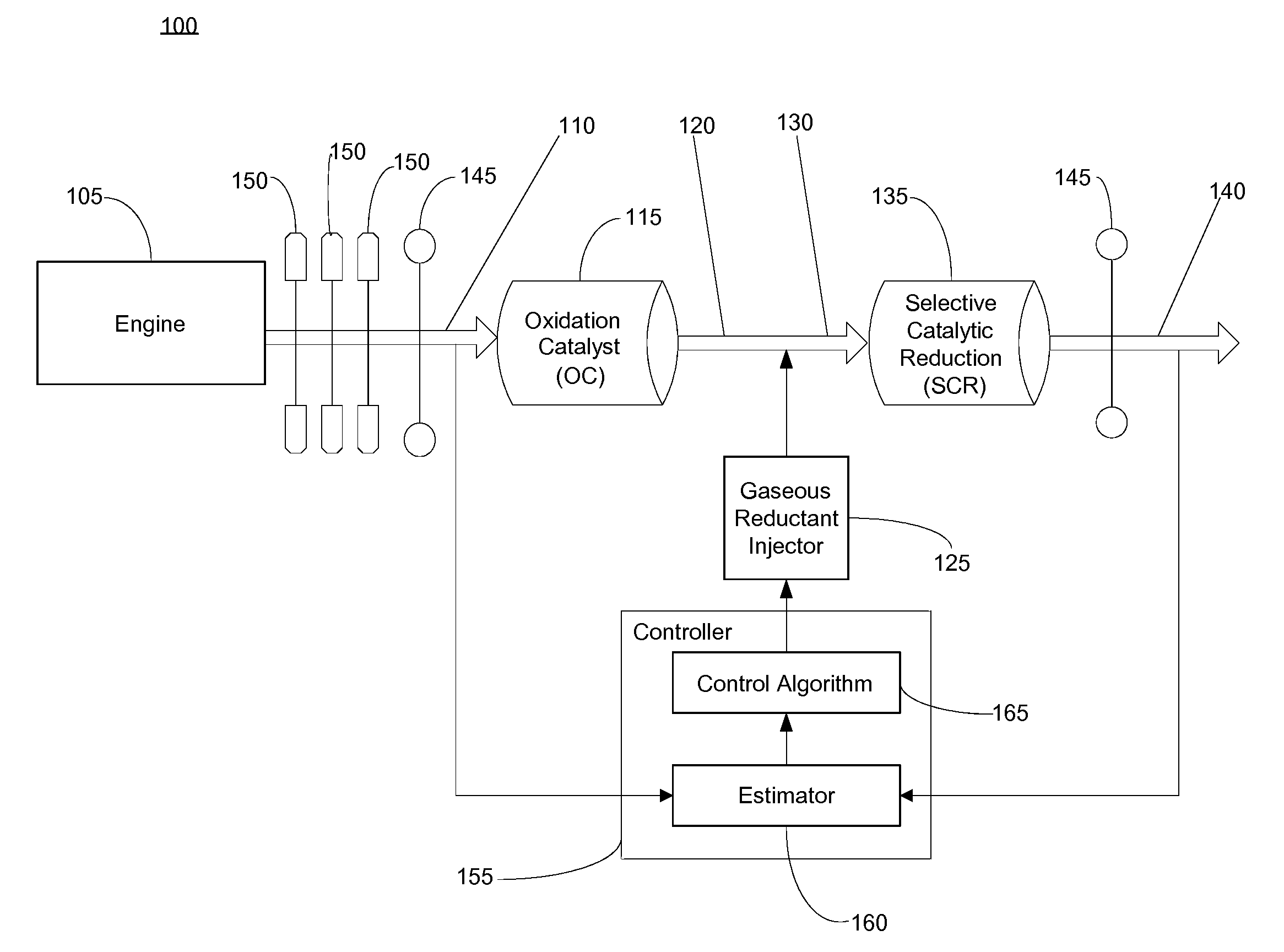
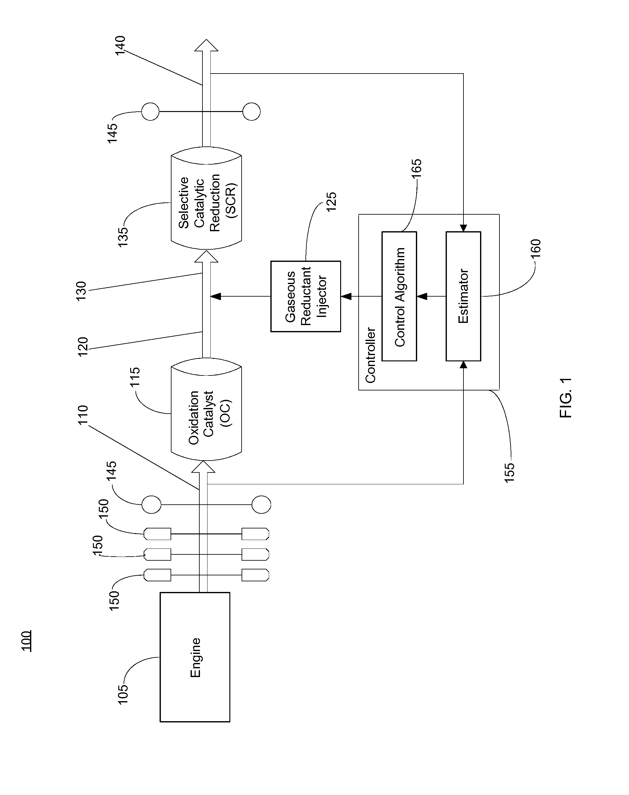
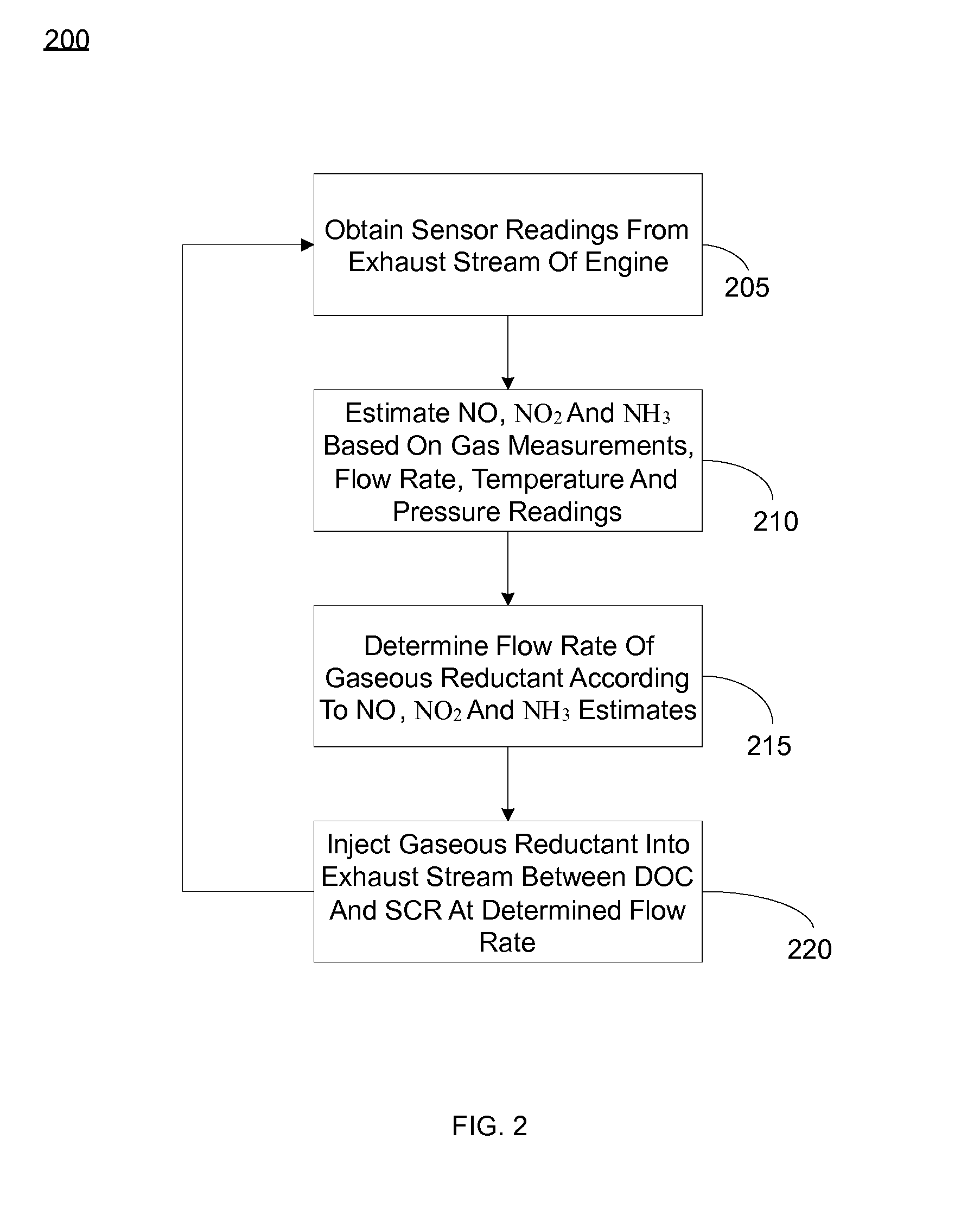
[0007]Various embodiments of the present invention are directed to estimating nitric oxide (NO), nitride dioxide (NO2) and ammonia (NH3) in exhaust gas generated from an engine such as a lean-burn engine in order to perform an aftertreatment on the exhaust such that nitrogen oxide (NOx) and NH3 emissions are reduced. In one embodiment, an exhaust stream generated from an engine is applied to an oxidation catalyst (OC) and a selective catalytic reduction (SCR) catalyst. A gaseous reductant injector injects a gaseous reductant into the exhaust stream between the OC and the SCR catalyst. Gas sensors located upstream of the OC and downstream of the SCR catalyst obtain measurements of the concentration of a gas in the exhaust stream. A controller, containing an estimator having models of the OC and the SCR catalyst, receives the gas concentration measurements along with other operating conditions out of the engine. In one embodiment, the estimator can estimate concentrations of NO and NO...


PUM


Abstract

A gaseous reductant injection control system for exhaust aftertreatment is disclosed. In one embodiment, a selective catalytic reduction (SCR) catalyst is in fluid communication with an exhaust stream generated from an engine. An oxidation catalyst (OC) is upstream of the SCR catalyst and in fluid communication with the exhaust stream. A gaseous reductant injector is upstream of the SCR catalyst and downstream of the OC and in fluid communication with the exhaust stream. A first gas sensor is upstream of the OC and a second gas sensor is downstream of the SCR catalyst. A controller receives signals representative of gas concentrations detected in the exhaust stream by the first gas sensor and the second gas sensor, and estimates concentrations of nitric oxide (NO) and nitride dioxide (NO2) in the exhaust stream therefrom.

Description

BACKGROUND OF THE INVENTION[0001]The present invention relates generally to reducing pollutant emissions from combustion processes, and more particularly, to a gaseous reductant injection control system for exhaust aftertreatment of nitrogen oxide (NOx) or ammonia (NH3) emissions generated from a lean-burn engine.[0002]Lean-burn engines, such as those used by diesel-powered and natural gas-powered vehicles, equipment, and generators combust at high air-to-fuel ratios in comparison with rich-burn engines. By nature, lean-burn engines use less fuel while producing equivalent power of similar-sized rich-burn engines. However, lean-burn engines have increased NOx and NH3 emissions generally due to slow burn rates associated with the lean mixtures of fuel (i.e., excess air introduced with the fuel). Aftertreatment options are typically used to reduce NOx and NH3 emissions from the exhaust of the lean-burn engines.BRIEF DESCRIPTION OF THE INVENTION[0003]In one aspect of the present invent...

Claims


Application Information

Patent Timeline
Patent Type & Authority Patents(United States)
IPC IPC(8): F01N3/00F01N3/10F01N3/20F01N3/18F01N9/00F01N3/02F01N13/00
CPCF01N3/18F01N3/103F01N3/208F01N3/2066F01N9/005F01N13/009F01N2560/021F01N2560/026F01N2560/06F01N2560/07F01N2560/08F01N2570/14F01N2610/02F01N2610/06F01N2900/0416F01N2900/1402F01N2900/1404F01N2900/1406F01N2900/1411Y02T10/12Y02T10/40
Inventor DEVARAKONDA, MARUTHI, NARASINGA, RAO
Owner AI ALPINE US BIDCO INC
Features
  • R&D
  • Intellectual Property
  • Life Sciences
  • Materials
  • Tech Scout
  • Unparalleled Data Quality
  • Higher Quality Content
  • 60% Fewer Hallucinations
Learn More