Modeling and simulating flow propagation in dynamic bandwidth systems

a dynamic bandwidth and flow propagation technology, applied in the field of network analysis, can solve the problems of complex analysis and planning, inability to determine the demand at subsequent links, and inability to establish and maintain an efficient network configuration to handle the increased flow, etc., to achieve the effect of effective and efficient prediction of flow characteristics

Active Publication Date: 2016-02-02
RIVERBED TECH LLC
View PDF7 Cites 2 Cited by
  • Summary
  • Abstract
  • Description
  • Claims
  • Application Information

AI Technical Summary

Benefits of technology

[0011]It would be advantageous to provide a flow propagation analysis technique that effectively and efficiently predicts flow characteristics in networks that include dynamic bandwidth links, such as contention-based links and other shared media communication links.

Problems solved by technology

As the demand for information flow continues to increase, establishing and maintaining an efficient network configuration to handle the increased flow typically requires complex analysis and planning.
Conventional flow propagation analysis techniques, however, have been found to be unsuitable for determining flows in networks that contain links with dynamic bandwidths, such as contention-based wireless links.
If the available bandwidth is variable, a fixed allocation cannot be determined, and consequently the demand at subsequent links cannot be determined.
In addition to creating dynamic flow characteristics for the traffic on the dynamic link, these mobile devices may also dynamically become neighboring links to other links, thereby affecting the traffic flow on these other links as well.
Although dynamic bandwidth is a particularly acute problem in contention-based links, it should be noted that the aforementioned neighboring link and mobile link effects can also affect links that are typically consider fixed-bandwidth links.
For example, if the distance between a device on the sub-network and a distant device is such that the distant device is likely to interfere with 5% of the communications being received at the device on the sub-network, causing the sub-network to retransmit the communications, the resultant reduction in effective bandwidth on the sub-network is dependent upon the relative amount of traffic that is flowing to the affected device on the sub-network.

Method used


Image

  • Modeling and simulating flow propagation in dynamic bandwidth systems
  • Modeling and simulating flow propagation in dynamic bandwidth systems
  • Modeling and simulating flow propagation in dynamic bandwidth systems

Examples


Embodiment Construction

[0019]In the following description, for purposes of explanation rather than limitation, specific details are set forth such as the particular architecture, interfaces, techniques, etc., in order to provide a thorough understanding of the concepts of the invention. However, it will be apparent to those skilled in the art that the present invention may be practiced in other embodiments, which depart from these specific details. In like manner, the text of this description is directed to the example embodiments as illustrated in the Figures, and is not intended to limit the claimed invention beyond the limits expressly included in the claims. For purposes of simplicity and clarity, detailed descriptions of well-known devices, circuits, and methods are omitted so as not to obscure the description of the present invention with unnecessary detail.

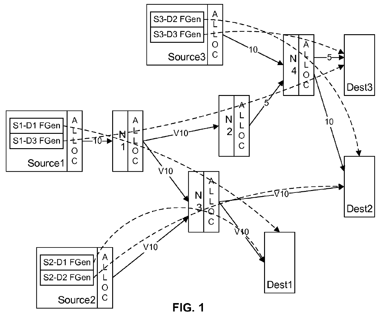
[0020]FIG. 1 illustrates an example flow network diagram that serves to illustrate an example use of this invention; one of skill in the art wil...


PUM


Abstract

In a network that includes static bandwidth and dynamic bandwidth links, traffic flow at the OSI network layer is simulated at a traffic-flow level at interfaces to fixed bandwidth links, and simulated at a discrete-packet level at interfaces to dynamic bandwidth links. The resultant discrete-packet reception events at the receiving interface(s) of the dynamic bandwidth link are processed to determine the effective bandwidth / throughput of the link, as well as the allocation of this bandwidth among the individual flows through the link. The discrete-packet level receptions are used to reconstruct the parameters of the traffic flow at the network layer of the receiving interface, and this determined traffic flow is simulated accordingly at the next link, depending upon whether the next link is a static or dynamic bandwidth link.

Description

[0001]This application claims the benefit of U.S. Provisional Patent Application 60 / 866,224, filed 17 Nov. 2006.BACKGROUND AND SUMMARY OF THE INVENTION[0002]This invention relates to the field of network analysis, and in particular to a method and system for assessing flows in a network that includes shared communications media.[0003]As the demand for information flow continues to increase, establishing and maintaining an efficient network configuration to handle the increased flow typically requires complex analysis and planning. Generally, the analysis includes the identification of ‘bottlenecks’ where information flow is substantially impeded, or is expected to be impeded with future increases in traffic flow, and the planning includes the replacement or upgrading of equipment, or a reconfiguration of the network topology, to remove such bottlenecks, based on ‘what-if’ analyses of the benefits provided if such equipment or topology changes are made.[0004]A common task for a netwo...

Claims


Application Information

Patent Timeline
Patent Type & Authority Patents(United States)
IPC IPC(8): G06F17/50G06G7/62H04L12/24
CPCH04L41/145H04L41/0896H04L41/22
Inventor CHANDRASHEKAR, KARTHIKEYANCOHEN, ALAIN J.JANES, PAUL M.BOYD, DAVIDZNAM, STEFANSINGH, PRADEEP
Owner RIVERBED TECH LLC
Why Eureka
Try Eureka