Contact image sensor unit including a detachable light guide supporting member and image reading apparatus using the same

a technology of contact image sensor and light guide supporting member, which is applied in the direction of solid-state devices, instruments, material analysis, etc., can solve the problems of poor conditions and terms of production management of the contact image sensor unit, and achieve the effects of improving quality, reducing the kinds of frames, and being easy to mold

Active Publication Date: 2016-02-02
CANON COMPONENTS INC
View PDF118 Cites 28 Cited by
  • Summary
  • Abstract
  • Description
  • Claims
  • Application Information

AI Technical Summary

Benefits of technology

[0042]According to the present invention, since a light guide can be attached to a frame without using an adhesive by providing a supporting member attachably / detachably supporting the light guide and attachably / detachably attached to a positioning part, the deformation of the light guide, the warpage of the contact image sensor unit and so on can be prevented to improve the quality. Further, the shape of the supporting member can be modified according to the shape of the light guide, so that the frame can be easily molded and the kinds of the frame can be reduced, thus making the production management more efficient.

Problems solved by technology

Here, when the light guide is fixed to the frame of the contact image sensor unit with an adhesive or the like, there are following problems.
Specifically, the materials of the frame and the light guide are different, thus possibly causing poor conditions such as the deformation of the light guide caused by the thermal expansion and / or contraction due to a change in environmental temperature, and the warpage of the contact image sensor unit and the like.
However, in this conventional technique, it is difficult to integrally mold the frame 406 and the elastic holding part 404 which needs to be made of a material having elastic characteristics different from that of the frame 406 and have a complicated shape in consideration of the shape and the detachability of the light guide 403 and the like.
Furthermore, there is a problem in terms of production management of the contact image sensor unit production as follows.

Method used


Image

  • Contact image sensor unit including a detachable light guide supporting member and image reading apparatus using the same
  • Contact image sensor unit including a detachable light guide supporting member and image reading apparatus using the same
  • Contact image sensor unit including a detachable light guide supporting member and image reading apparatus using the same

Examples


embodiment 1

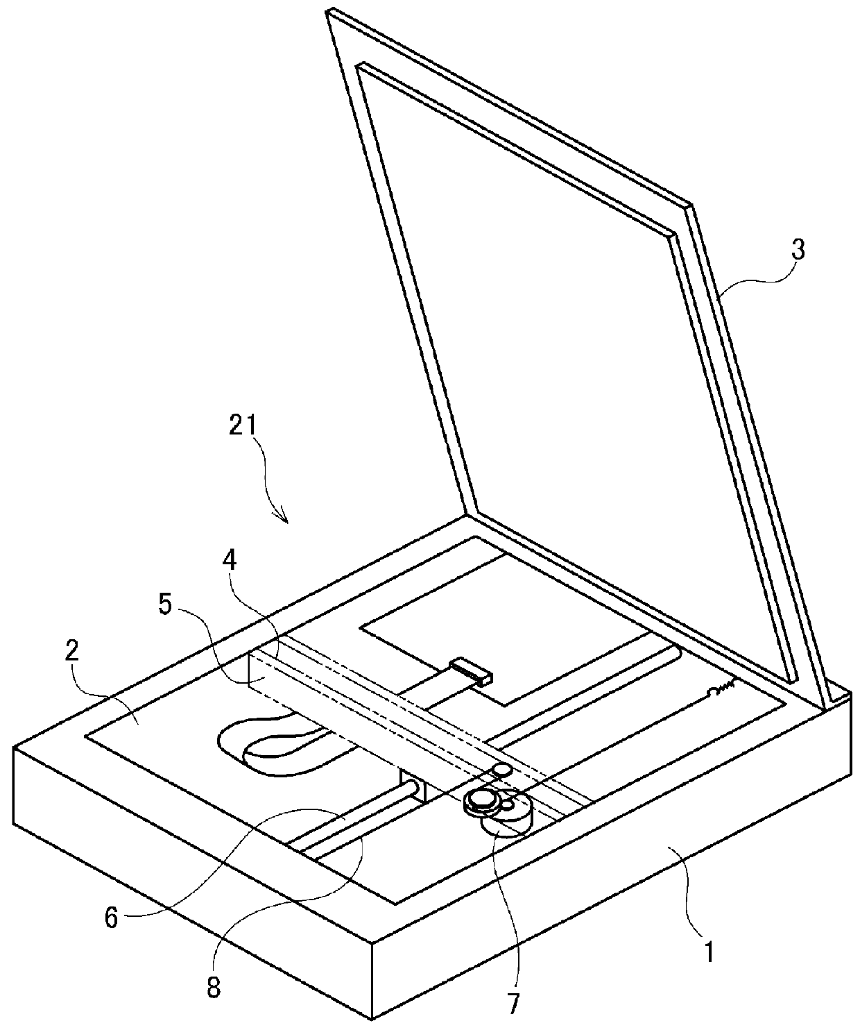
[0062]FIG. 1 is a perspective view illustrating the structure of a flatbed-type scanner (image reading apparatus) to which the present invention is applicable.

[0063]A numeral 1 denotes a casing. The casing 1 is provided with a platen glass 2 composed of a transparent plate made of glass as an original placing part, and a platen cover 3 provided to freely open and close in a manner to cover the original placed on the platen glass 2.

[0064]Further, inside the casing 1, a CIS unit 4 to which the present invention is applicable is stored. A numeral 5 denotes a holding member holding the CIS unit 4 in a manner to surround it. A numeral 6 denotes a slide shaft provided to be capable of moving the holding member 5 along the platen glass 2. A numeral 7 denotes a drive motor. A numeral 8 denotes a wire.

[0065]With this configuration, the drive motor 7 is driven to mechanically move the wire 8 attached to the holding member 5 to thereby move the CIS unit 4 in a reading direction (sub-scan direc...

embodiment 2

[0114]This embodiment is the invention in which the locking grooves 201 are not formed in the positioning part 200 as in the embodiment 1, but a holder 16 as a supporting member gripping and supporting a light guide 11 is made attachably / detachably attached to a positioning part 500. Hereinafter, the details of the invention of the embodiment 2 will be described using FIG. 11 to FIG. 13 in addition to the drawings used for the description of the embodiment 1. The same components as those in the description of the embodiment 1 are made to correspond to them by giving the same numerals and symbols to the components. However, the frame and parts and elements directly related with the frame are characterized in that there is no locking groove therein, and are newly given numerals in the 500s. The light guide 11 and the light source 10 constituting the illumination device in the embodiment 1 can be used as they are. The basic function and the configuration of the holder 16 itself do not ...

example 1

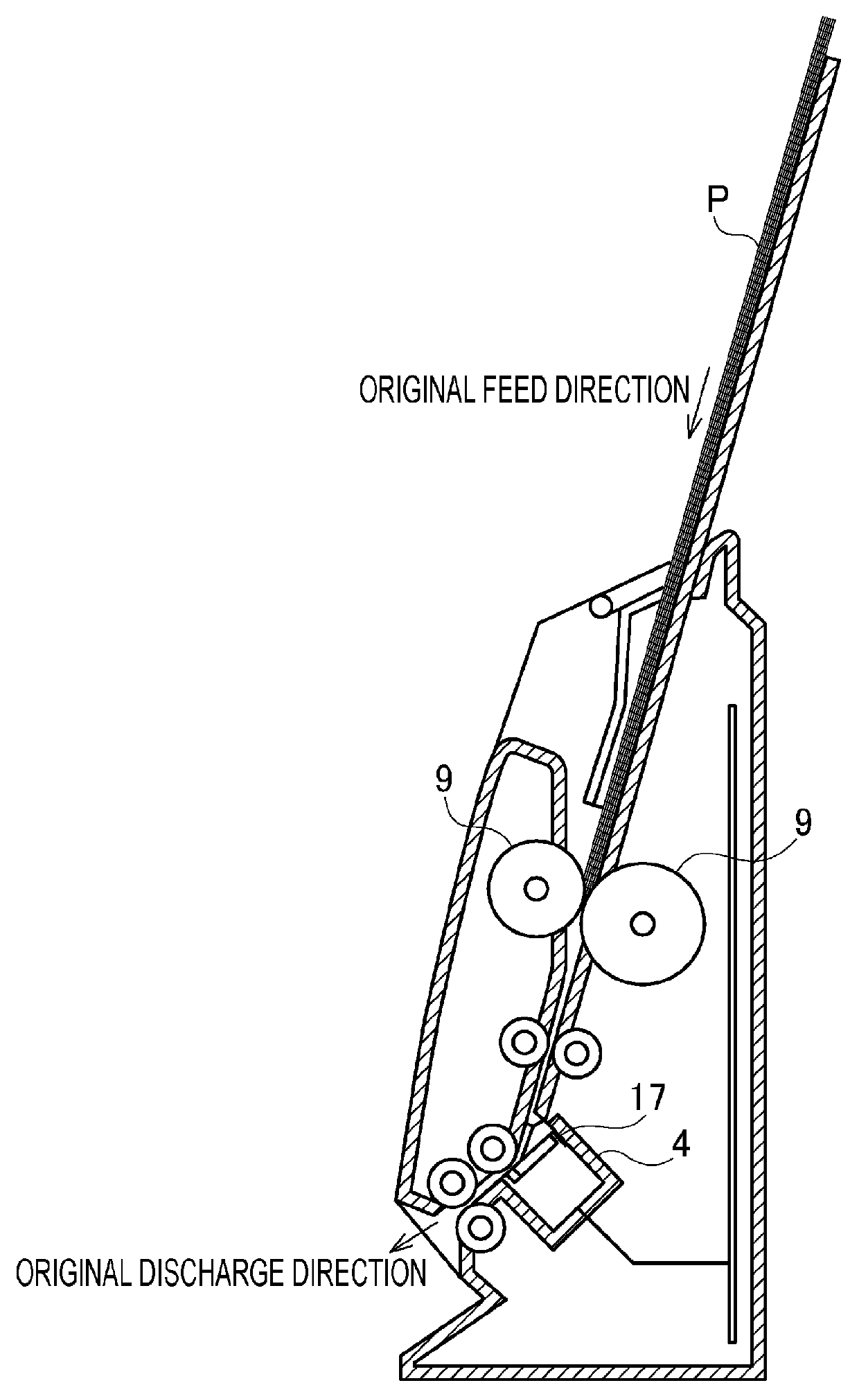
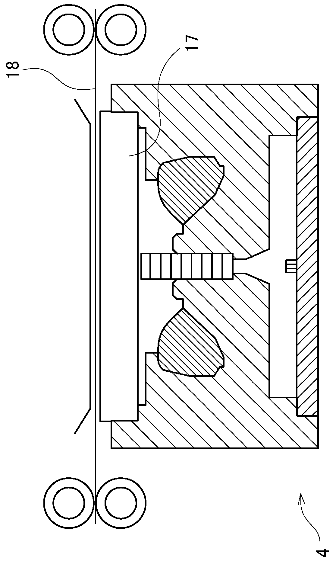
[0127]An example 1 corresponds to a CIS unit for use in the sheetfeed-type image reading apparatus with a cover glass attached thereto. In particular, the example 1 is a CIS unit intended for the image reading apparatus with a small original width and is advantageous in the case where the length of the light guide is relatively short. The light guide in such a CIS unit has a sectional shape in the sub-scan direction with a small difference depending on the position in the longitudinal direction or has the same sectional shape over almost the whole length. Even in this sectional shape, the difference in luminance distribution in the longitudinal direction of the light guide is small. Hereinafter, the details of the example 1 will be described.

[0128]In the example 1, three pieces of the same holder 16 were produced. The holders 16 are formed to have an outside dimension inscribed in the positioning part 500 and to have the same inner size “a” of the annular shape illustrated in FIG. 8...


PUM


Abstract

A contact image sensor unit includes: a light source (10) illuminating an original; a rod-like light guide (11) guiding light from the light source to the original; an imaging element (12) forming reflected light from the original on a plurality of photoelectric conversion elements; a sensor substrate (14) on which the plurality of photoelectric conversion elements are mounted; a frame (15) to which they are attached and which has a positioning part (200) for attaching the light guide (11) thereto; and a supporting member (16) which attachably / detachably supports the light guide (11) and is attachably / detachably attached to the positioning part (200). Since the light guide (11) can be attached to the frame (15) without using an adhesive, the deformation of the light guide (11), the warpage of the contact image sensor unit and so on can be prevented.

Description

CROSS-REFERENCE TO RELATED APPLICATIONS[0001]This application is a National Stage application of, and claims priority from, PCT Application No. PCT / JP2010 / 069500, filed on Nov. 2, 2010.TECHNICAL FIELD[0002]The present invention relates to a contact image sensor unit and an image reading apparatus suitable for an image scanner, facsimile, copying machine and so on. In particular, the present invention relates to a contact image sensor unit including an illumination device composed of a light source and a rod-like light guide for illuminating an original surface, and an image reading apparatus using it.BACKGROUND ART[0003]In the image reading apparatus such as an image scanner, copying machine and so on, a contact image sensor unit which is brought into close contact with the original to read the original at the same magnification has been conventionally used as the image sensor optically reading image information on the original and converting the information into electric signals.[0...

Claims


Application Information

Patent Timeline
Patent Type & Authority Patents(United States)
IPC IPC(8): H04N1/31H04N1/28H04N1/031H04N1/028
CPCH04N1/0318H04N1/02835H04N2201/02435H04N2201/02445H04N2201/02456H04N2201/02458H04N2201/02462H04N2201/02464H04N2201/02472H04N2201/02474H04N2201/02483H04N2201/02485H04N2201/03112H04N2201/03125H04N2201/03129H04N2201/03141H04N2201/03145H04N1/028
Inventor TAKAHASHI, HIDEHISA
Owner CANON COMPONENTS INC
Why Eureka
Try Eureka