
Automatic water supply-type steam generator using vapor pressure

a technology of automatic water supply and steam generator, which is applied in the direction of steam generation using hot heat carriers, water feed control, separation processes, etc., can solve the problems of disadvantageous maintenance costs of such facilities, inability to reliably perform water supply, and difficulty in obtaining high energy efficiency and operation performance, so as to achieve the effect of continuous and effective supply of necessary vapor, unnecessary power consumption, and considerable savings in the cost of related facilities

Active Publication Date: 2016-02-09
YIM JOO HYUK
View PDF14 Cites 0 Cited by
  • Summary
  • Abstract
  • Description
  • Claims
  • Application Information

AI Technical Summary

Benefits of technology

The present invention helps to generate vacuum pressure in a pressurization water supply tank, using vapor pressure to suck water from a condensation water collection tank and automatically supplementing it into the tank. This allows for continuous and effective supply of necessary vapor to a steam generator. Compared to conventional art, this invention eliminates the need for large capacity pumps, saving costs and avoiding unnecessary power consumption. The invention also ensures a constant level of vacuum by freely adjusting the vacuum pressure forming in the tank, overcoming the problem of vacuum pressure affecting the steam tank.

Problems solved by technology

Since the interior of the steam tank maintains a high pressure itself, even when the water supply tank is provided at the top, water supply is not reliably performed.
So as to overcome the above mentioned problems, it needs to install a motor pump with a large capacity, which is costly in installing related facilities, and it entails more electric power for the sake of a start and operations of a motor pump, so it is hard to obtain a high energy efficiency and operation performance, and the maintenance of such facilities is disadvantageously costly.

Method used


Image

  • Automatic water supply-type steam generator using vapor pressure
  • Automatic water supply-type steam generator using vapor pressure
  • Automatic water supply-type steam generator using vapor pressure

Examples


Embodiment Construction

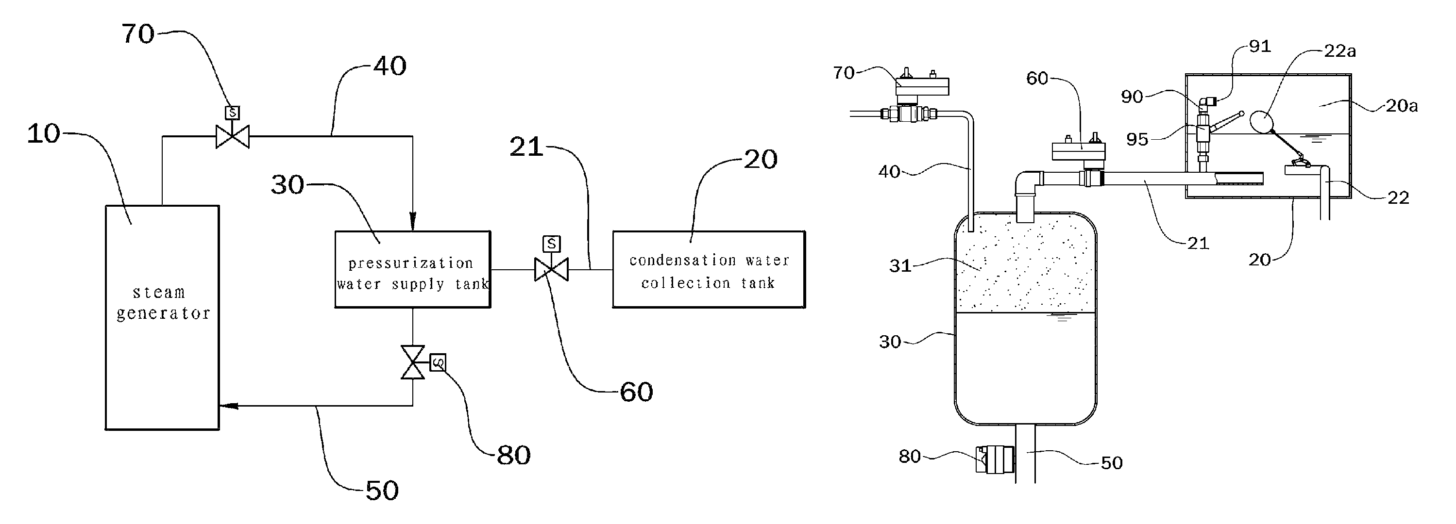
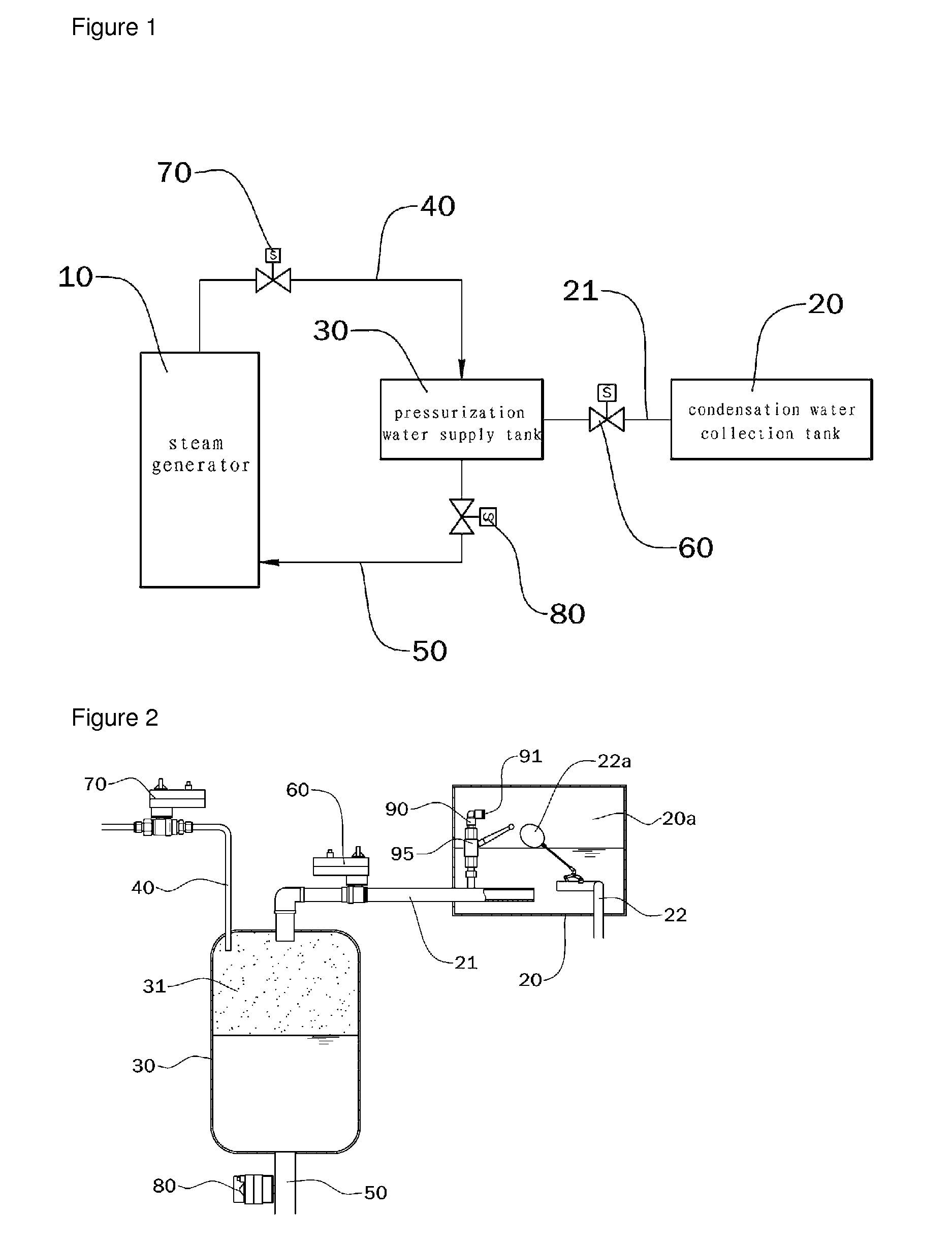
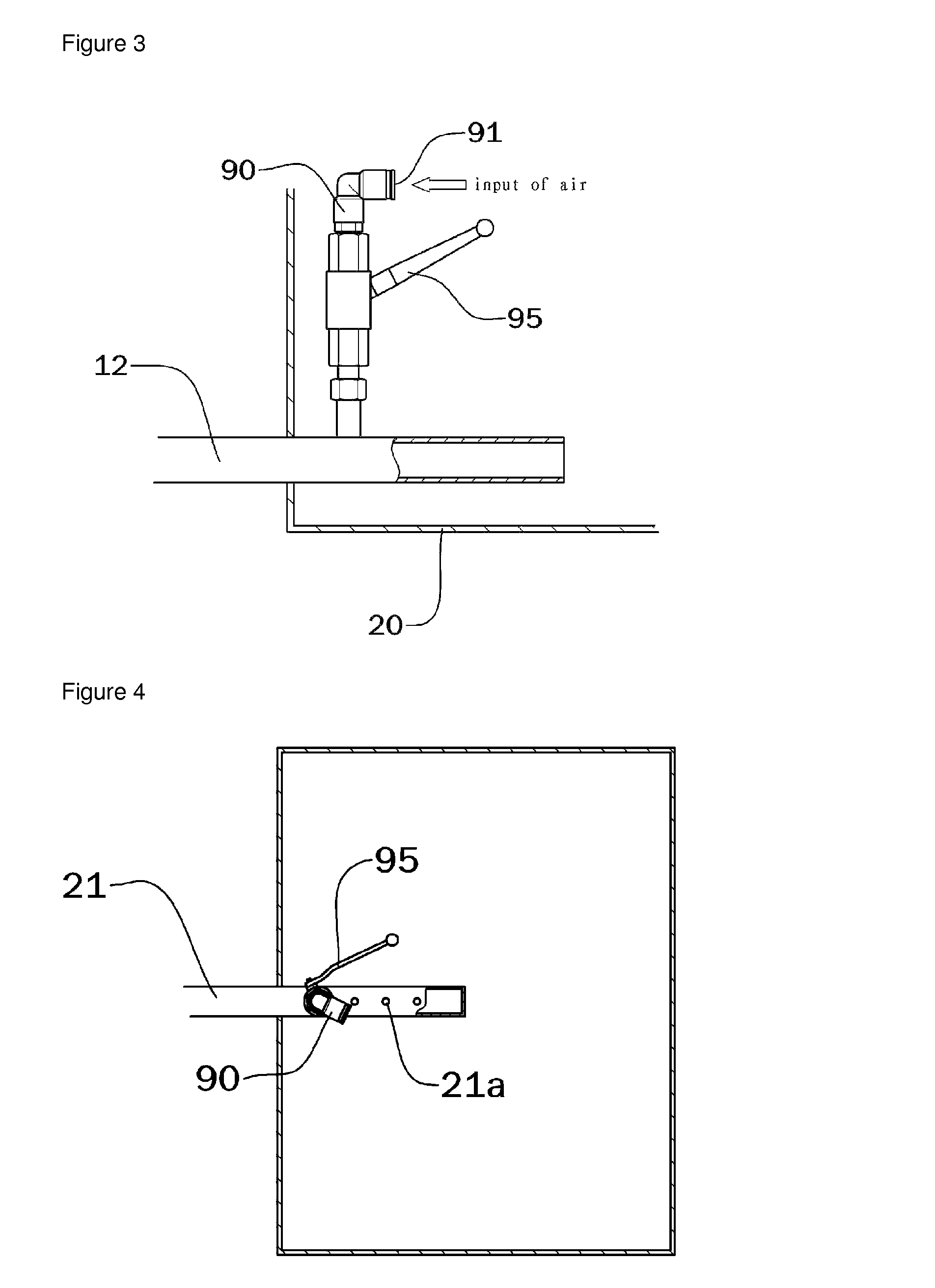
[0023]The whole technical construction according to a preferred embodiment of the present invention will be described in details. There are provided a condensation water collection tank 20 which collects spent steam; a pressurization water supply tank 30 which is installed through the condensation water collection tank 20 and a water supplement tube 21; a vapor pressure supply tube 40 connected between the pressurization water supply tank 30 and a steam generator 10; a water supply tube 50 which is connected either between the pressurization water supply tank 30 and the steam generator 10; a water supplement control valve 60 installed at a pipe conduit of the water supplement tube 21; a pressure supply control valve 70 which is installed at a pipe conduit of the vapor pressure supply tube 40; a water supply control valve 80 which is installed at a pipe conduit of the water supply tube 50; and an air vent 90 which is branched and installed at the water supplement tube 21 so as to adj...


PUM

PropertyMeasurementUnit
vapor pressureaaaaaaaaaa
internal vacuum pressureaaaaaaaaaa
vacuum pressureaaaaaaaaaa

Abstract

The present invention relates to an automatic water supply-type steam generator using vapor pressure for creating the optimum vacuum pressure inside a pressurized water supply tank, and for smoothly providing water to the pressurized water supply tank by using the strong aspiration force that is created by means of the vacuum pressure while continuously generating steam. The present invention is characterized by allowing control of the vacuum pressure to the optimum state when creating the vacuum pressure inside the pressurized water supply tank by introducing an adequate amount of outside air from the atmosphere through an air vent. In addition, the present invention is characterized by providing a means for cooling the pressurized water supply tank so as to control the vacuum pressure inside the tank to the optimum state.

Description

RELATED APPLICATIONS[0001]This application is a 371 application of International Application No. PCT / KR2011 / 010266, filed Dec. 28, 2011, which in turn claims priority from Korean Patent Application Nos. 10-2011-0014264, filed Feb. 17, 2011, and 10-2010-0136553, filed Dec. 28, 2010, each of which is incorporated herein by reference in its entirety.TECHNICAL FIELD[0002]The present invention relates to an automatic water supply-type steam generator using a vapor pressure which makes it possible to generate the optimum vacuum pressure in the interior of a pressurization water supply tank using a vapor pressure and to continuously generate necessary steam while reliably supplying water to the pressurization water supply tank with the aid of a strong suction force which is generated by the vacuum pressure.BACKGROUND ART[0003]A steam generator is configured in such a way that a water level detection sensor detecting the level of water is installed in a steam tank which helps generate and s...

Claims


Application Information

Patent Timeline
Patent Type & Authority Patents(United States)
IPC IPC(8): F22D5/26F22D5/28
CPCF22D5/28F22B1/00F22D5/00F22B1/18F22D5/26F22D5/30
Inventor YIM, JOO, HYUK
Owner YIM JOO HYUK
Learn More