Clutch torque trajectory correction to provide torque hole filling during a ratio upshift

a technology of torque hole filling and torque hole, which is applied in the direction of gearing control, coupling-brake combination, gearing elements, etc., can solve the problems of inability to accurately estimate in real time the torque of the clutch, the non-linearity of the clutch actuator, and the influence of the response to the control pressure. , to achieve the effect of reducing the torque hole effect and reducing the disturbance of transient torqu

Inactive Publication Date: 2016-02-16
FORD GLOBAL TECH LLC
View PDF54 Cites 5 Cited by
  • Summary
  • Abstract
  • Description
  • Claims
  • Application Information

AI Technical Summary

Benefits of technology

[0005]An objective of the present invention is to eliminate or reduce the torque hole effect while reducing transient torque disturbances during an upshift event. A transmission controller can provide estimated friction element torque targets using friction el...

Problems solved by technology

The algorithms, if used without the actual torque feedback provided by the sensors, do not have the ability to accurately estimate in real time the clutch torques during an upshift.
The clutch actuators, how...

Method used


Image

  • Clutch torque trajectory correction to provide torque hole filling during a ratio upshift
  • Clutch torque trajectory correction to provide torque hole filling during a ratio upshift
  • Clutch torque trajectory correction to provide torque hole filling during a ratio upshift

Examples


Embodiment Construction

[0024]As required, detailed embodiments of the present invention are disclosed herein; however, it is to be understood that the disclosed embodiments are merely exemplary of the invention that may be embodied in various and alternative forms. The figures are not necessarily to scale; some features may be exaggerated or minimized to show details of particular components. Therefore, specific structural and functional details disclosed herein are not to be interpreted as limiting, but merely as a representative basis for teaching one skilled in the art to variously employ the present invention.

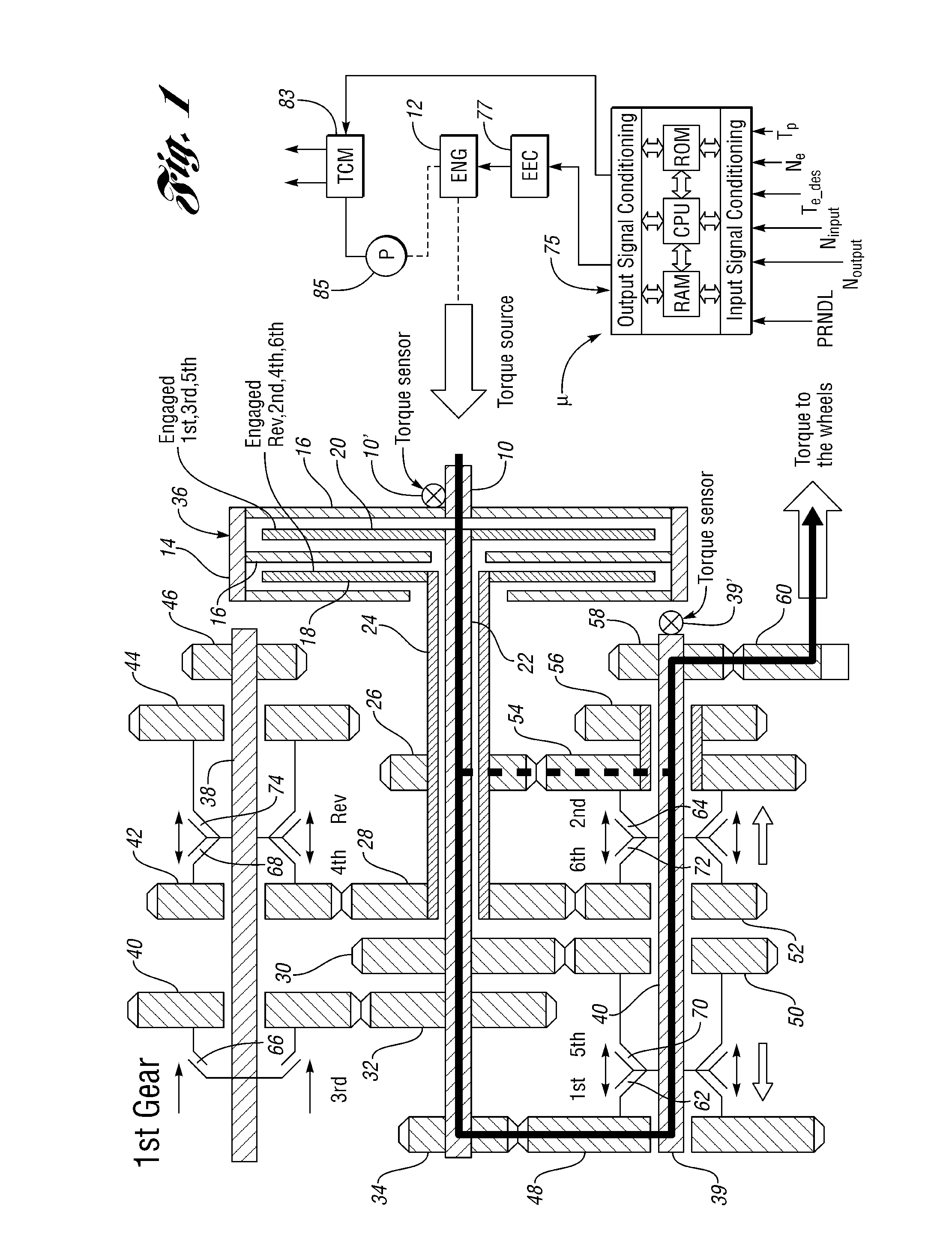
[0025]FIG. 1 shows in schematic form a lay-shaft transmission capable of embodying the invention together with a schematic representation of the transmission components involved in gear ratio changes.

[0026]Numeral 10 represents a power input shaft drivably connected to torque source 12. Input shaft 10 drives a clutch housing 14, which carries torque input driving discs 16 situated in interdigital...


PUM


Abstract

A control system and method for controlling a multiple gear ratio automatic transmission in a powertrain for an automatic transmission having pressure activated friction torque elements to effect gear ratio upshifts. The friction torque elements are synchronously engaged and released during a torque phase of an upshift event as torque from a torque source is increased while allowing the off-going friction elements to slip, followed by an inertia phase during which torque from a torque source is modulated. A perceptible transmission output torque reduction during an upshift is avoided. Measured torque values are used during a torque phase of the upshift to correct an estimated oncoming friction element target torque so that transient torque disturbances at an oncoming clutch are avoided and torque transients at the output shaft are reduced.

Description

CROSS-REFERENCE TO RELATED APPLICATIONS[0001]This application is a continuation of U.S. application Ser. No. 13 / 155,867, filed Jun. 8, 2011, now issued as U.S. Pat. No. 8,775,044, the disclosure of which is hereby incorporated in its entirety by reference herein.TECHNICAL FIELD[0002]The invention relates to a multiple ratio transmission mechanism in a powertrain for an automotive vehicle and to a strategy for achieving smooth engagement and release of friction torque establishing elements during a transmission ratio upshiftBACKGROUND[0003]A step-ratio automatic transmission uses multiple friction elements for automatic gear ratio shifting. A ratio change from a low gear ratio to a high gear ratio occurs in a synchronous clutch-to-clutch upshift as one friction element is engaged and a second friction element is disengaged. One friction element may be referred to as an off-going clutch (OGC). It is released while a second friction element, which may be referred to as an oncoming clut...

Claims


Application Information

Patent Timeline
IPC IPC(8): B60W10/18F16H59/16F16H61/06B60W10/115B60W10/02F16D67/02F16H61/04
CPCB60W10/115B60W10/02F16D67/02F16H59/16F16H61/061F16H2061/0462Y10T477/641Y10T477/6425F16H61/0403B60W10/06B60W30/19B60W50/06B60W2050/0008B60W2050/0043B60W2510/0275B60W2510/105B60W2710/025B60W2710/027B60W2710/0666B60W2710/105
Inventor TESLAK, CHRISTOPHER JOHNPIETRON, GREGORY MICHAELTSENG, HONGTEI ERICFUJII, YUJIFODOR, MICHAEL GLENNYANAKIEV, DIANALEE, SEUNG-HOON
Owner FORD GLOBAL TECH LLC
Why Eureka
Try Eureka