Vacuum gripper

a vacuum gripper and vacuum technology, applied in the direction of vacuum grippers, lighting and heating apparatuses, furnace components, etc., can solve the problems of workpiece overflow, workpiece overflow, and high cost of control of such highly dynamic processes

Active Publication Date: 2016-02-23
ZIMMERMANN & SCHILP HANDHABUNGSTECHN
View PDF23 Cites 6 Cited by
  • Summary
  • Abstract
  • Description
  • Claims
  • Application Information

AI Technical Summary

Benefits of technology

[0015]Therefore, subject matter of the invention is to provide a reliable and low-cost device enabling also smooth plates requiring a great breakaway force to be lifted in a non-contact way.

Problems solved by technology

However, due to the high contact pressure, the surface of work-piece can be changed undesirably.
Therefore, during the procedure of gripping, there is a problem which will be explained below:
However, it would be desirable to reduce the suction power before the work-piece reaches its final position, because otherwise, there is the danger that, caused by its mass force of inertia, the accelerated work-piece overcomes the force generated by the air bearing and hits against the surface of gripper.
An expert knows that the control of such highly dynamic processes is extremely complex and thus costly, because it is difficult to control gaseous media, conditioned by the compressibility thereof.

Method used


Image

  • Vacuum gripper
  • Vacuum gripper
  • Vacuum gripper

Examples


Embodiment Construction

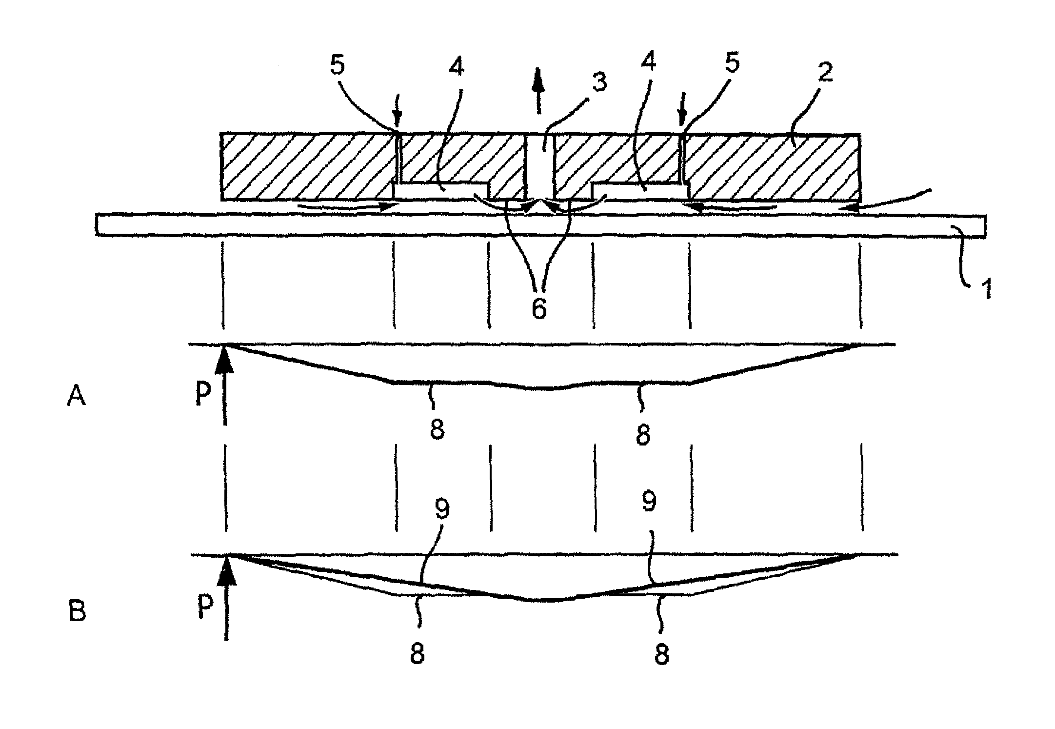
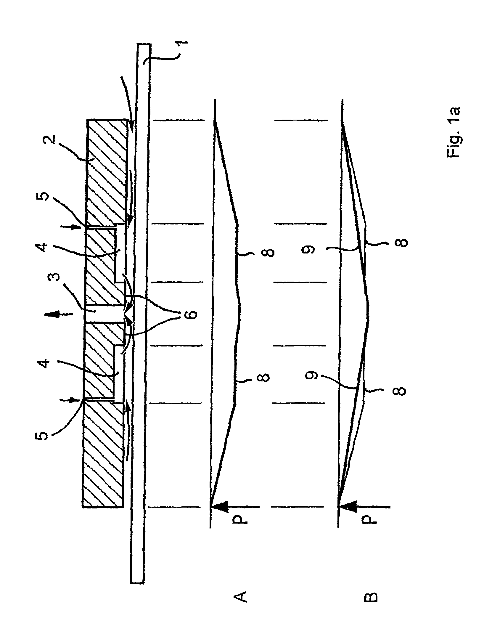
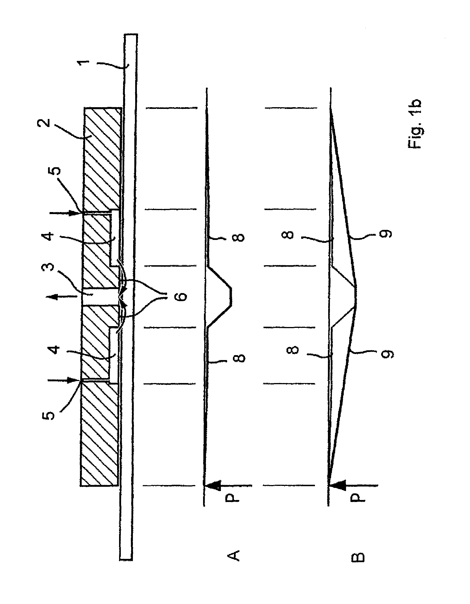
[0043]FIGS. 1a, b show a cross-sectional view of a circular vacuum gripper for carrying a work-piece 1, wherein the vacuum gripper comprises the following features: a disk-shaped round gripper plate 2 provided with a suction port 3 in its center. A round annular work-piece throttling zone 6 is formed around the suction port 3, the operating characteristics of which being explained in the consecutive section. The gripper plate 2 is also provided with an annular recess 4 extending towards the margin of plate, which has two vent holes 5 dislocated to each other by 180 degrees, that is, the entire recess 4 is connected with the atmosphere.

[0044]FIG. 1a shows the work-piece 1 still in its initial position. By the suction action of the gripper, air is sucked from the outside of gripper through the gap 7 usually having a width of about 2 mm to 0.8 mm and flows through the suction port 3. In this position, the vacuum gripper generates its maximum suction force being greater than the weight ...


PUM


Abstract

A vacuum gripper for gripping a work-piece includes a flat or curved gripper plate having at least one suction port. A work-piece suction throttling zone is formed around the suction port. The gripper plate has at least one recess provided at a side facing the work-piece and arranged beyond the work-piece suction throttling zone (6) formed around the suction port. At least one vent hole is formed within each of the recesses.

Description

CROSS-REFERENCES TO RELATED APPLICATIONS[0001]This application is a continuation of prior filed U.S. application Ser. No. 13 / 386,593, filed May 7, 2012, the priority of which is hereby claimed under 35 U.S.C. §120 and which is the National Stage of International Application No. PCT / DE2010 / 000860, filed Jul. 22, 2010, which designated the United States and has been published as International Publication No. WO 2011 / 009446 and which claims the priority of German Patent Application, Serial No. 10 2009 039 474.8, filed Jul. 22, 2009, pursuant to 35 U.S.C. 119(a)-(d).[0002]The contents of U.S. application Ser. No. 13 / 386,593, International Application No. PCT / DE2010 / 000860, and German Patent Application, Serial No. 10 2009 039 474.8 are incorporated herein by reference in their entirety as if fully set forth herein.BACKGROUND OF THE INVENTION[0003]The present invention relates to a vacuum gripper and, in particular, to a vacuum gripper for gently gripping work-pieces having sensitive sur...

Claims


Application Information

Patent Timeline
Patent Type & Authority Patents(United States)
IPC IPC(8): B25B11/00B65G47/91B65G49/06H01L21/683B25J15/06
CPCB65G47/91B25J15/0616B65G47/911B65G49/061H01L21/6838B65G2249/04
Inventor SCHILP, MICHAELZIMMERMANN, JOSEFZITZMANN, ADOLF
Owner ZIMMERMANN & SCHILP HANDHABUNGSTECHN
Why Eureka
Try Eureka