Electronic module and method for the production thereof

a technology of electronic modules and production methods, applied in the direction of electric apparatus casings/cabinets/drawers, printed circuit non-printed electric components association, vehicle sub-unit features, etc., to achieve cost-effective, convenient to use, and easy to be equipped

Active Publication Date: 2016-02-23
ROBERT BOSCH GMBH
View PDF24 Cites 1 Cited by
  • Summary
  • Abstract
  • Description
  • Claims
  • Application Information

AI Technical Summary

Benefits of technology

[0003]The inventive electronic module has in contrast the advantage that a cost effective electronic module which can easily be equipped can be provided, wherein electronic and / or electric components, in particular sensors and / or actuators, can be disposed at arbitrary positions. According to the invention, a cost effective, extensive support plate, e.g. a printed circuit board, or a ceramic or a substrate, can be used. As a result, the components can be mounted in a normal surface-mount process (SMT process) and therefore very cost-effectively. This is achieved according to the invention by the fact that the support plate comprises a base area and a connection element. The connection element is a part of the base area and is arranged at an angle to said base area, i.e. said connection element is integrally formed with the base area and protrudes from said base area. The connection element is arranged by bending the base area upward at an arbitrary angle to said base area. According to the invention, at least one component is thereby disposed on the connection element. By bending the connection elements upward from the base plane, a component can therefore be disposed according to the invention at an arbitrary position and at an arbitrary distance from the base plane. As a result, different sensors can, for example, be disposed at various positions which are spaced differently from the base area, only one single support plate being necessary in this arrangement. Temperature sensors, pressure sensors or rotational speed sensors can, for example, be used as sensors. The connection elements are preferably bent at an angle of 90° to the base area. Any other angle is, however, also conceivable.
[0005]The component is furthermore preferably disposed in an end portion of the connection element. In addition, the connection element and / or the support plate is surrounded by a sealing compound or the like. As a result, the connection element can be quickly and simply fastened to a counter body.
[0007]In a further preferred manner, the electronic module comprises a base plate, in particular a sheet metal plate, wherein the support plate is disposed on the base plate, in particular laminated to said base plate. As a result, the electronic module gains stability on the one hand and the base plate can furthermore be used for cooling. The region of the base plate located under the connection element is likewise preferably exposed and bent.

Problems solved by technology

As a result, the components can be mounted in a normal surface-mount process (SMT process) and therefore very cost-effectively.

Method used


Image

  • Electronic module and method for the production thereof
  • Electronic module and method for the production thereof
  • Electronic module and method for the production thereof

Examples


Embodiment Construction

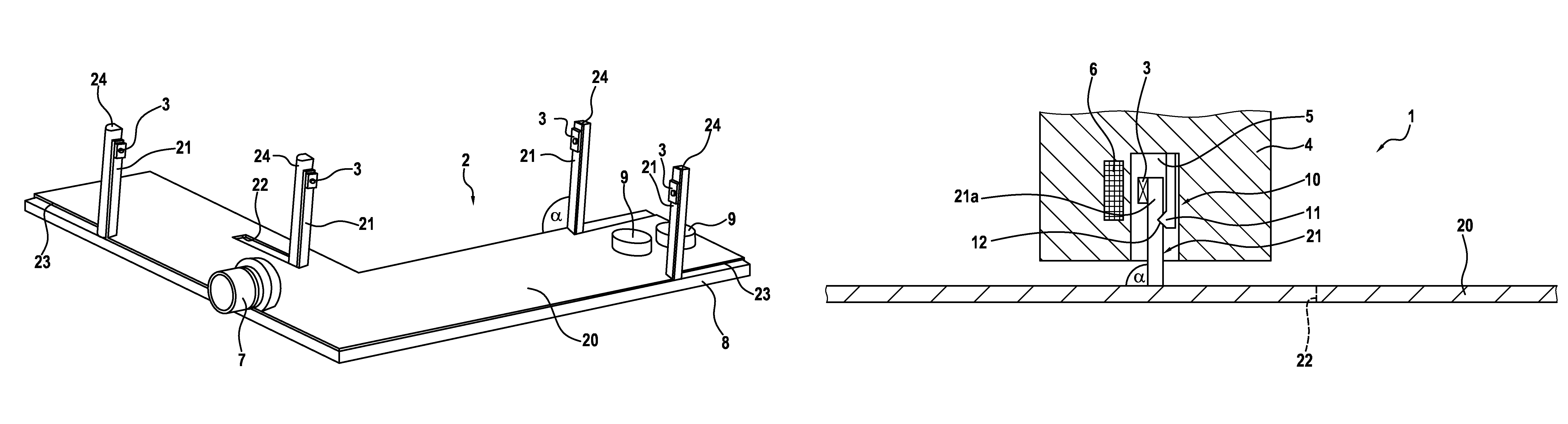
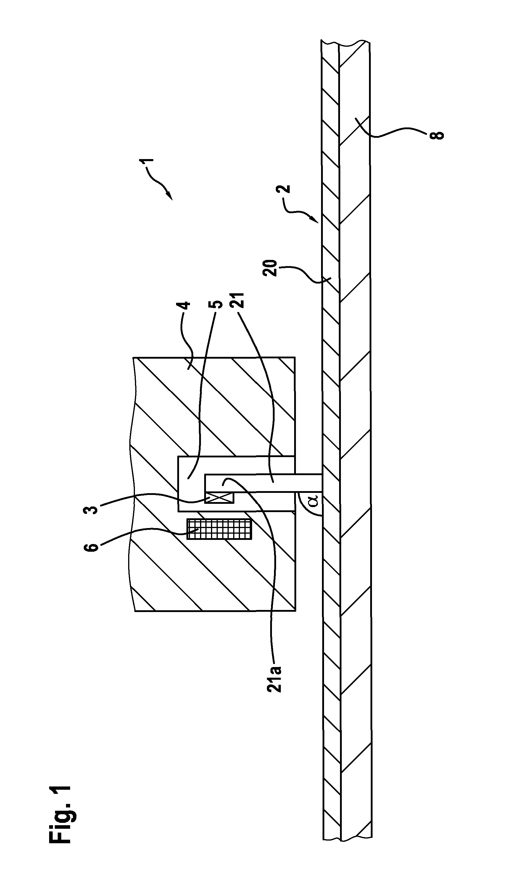
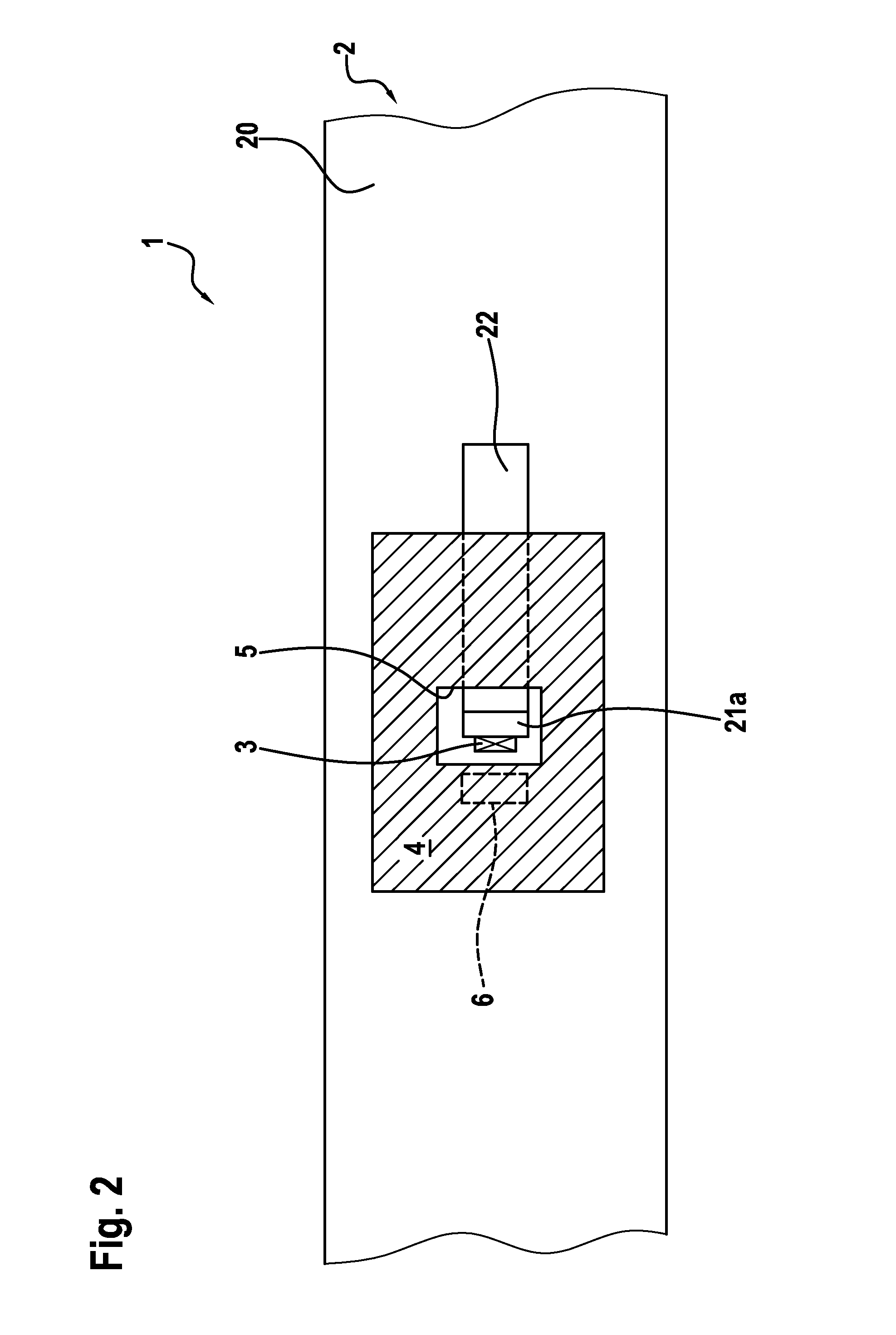
[0017]An electronic module 1 pursuant to a first preferred exemplary embodiment of the invention is described below in detail with reference to FIGS. 1 to 3.

[0018]As can especially be seen from FIG. 1, the electronic module 1 comprises a support plate 2, which is a printed circuit board in this exemplary embodiment. The support plate 2 has a base area 20 and a plurality of connection elements 21 (cf. FIG. 3), which are tilted upward from the base area 20 at an angle α of 90°. The printed circuit board is thereby an inexpensive, extensive printed circuit board and serves as a connection printed circuit board. The electronic module 1 further comprises electronic and / or electric components 3, which are sensors in this exemplary embodiment. The sensors are thereby in each case disposed in an end portion 21a of the connection elements 21.

[0019]The connection elements 21 can be produced by means of milling one side of the support plate, a recess 23 being formed in an edge region of the su...


PUM

PropertyMeasurementUnit
angleaaaaaaaaaa
widthaaaaaaaaaa
non-zero angleaaaaaaaaaa

Abstract

The invention relates to an electronic module, a support plate (2) having a base area (20) and at least one connection element (21). Said connection element (21) is a part of the base area (20) and is arranged at an angle (a) to the base area (20), in addition to at least one electronic component (3), in particular a sensor, which is arranged in the connection element (21).

Description

BACKGROUND OF THE INVENTION[0001]The present invention relates to an electronic module, as, for example, a transmission controller for motor vehicles, as well as to a method for the production thereof.[0002]In the prior art, a plurality of sensors is required at multiple locations, for example, in transmission control systems in order to acquire different signals, as, e.g., temperature, pressure and rotational speed. Feed lines to said sensors consist, for example, of flex foils or cables and are connected to the transmission controller which typically comprises a small printed circuit board. As a result, a very large assembly outlay is incurred and the necessary connections between sensors and printed circuit board are relatively expensive. In addition, a large number of procedural steps, as, e.g., bonding, soldering, welding or adhesive bonding, are required. It would therefore be desirable to provide a cost effective electronic module which particularly can be used in transmissio...

Claims


Application Information

Patent Timeline
Patent Type & Authority Patents(United States)
IPC IPC(8): H05K1/18H05K1/02F16H61/00H05K5/00H05K3/30H05K3/00
CPCH05K1/181F16H61/0006H05K1/0278H05K3/30H05K5/0082B60Y2400/30H05K1/028H05K1/0284H05K3/0061H05K2201/09081H05K2201/10151H05K2203/302Y10T29/4913
Inventor BRAUN, HOLGERBUBECK, HELMUTLAUSMANN, MATTHIASSCHINZEL, RALFVOIGTLAENDER, KLAUSMUELLER, THOMASBERTSCH, BENJAMIN
Owner ROBERT BOSCH GMBH
Why Eureka
Try Eureka