
Spreader device

a technology of material spreading and spherical rod, which is applied in the direction of centrifugal wheel fertilisers, construction, agriculture, etc., can solve the problems of excessive material spreading, inability to easily spread small amounts, and not well suited to small surfaces, etc., and achieve the effect of slow rotation of the spherical rod

Active Publication Date: 2016-03-01
DOUGLAS DYNAMICS
View PDF5 Cites 7 Cited by
  • Summary
  • Abstract
  • Description
  • Claims
  • Application Information

AI Technical Summary

Benefits of technology

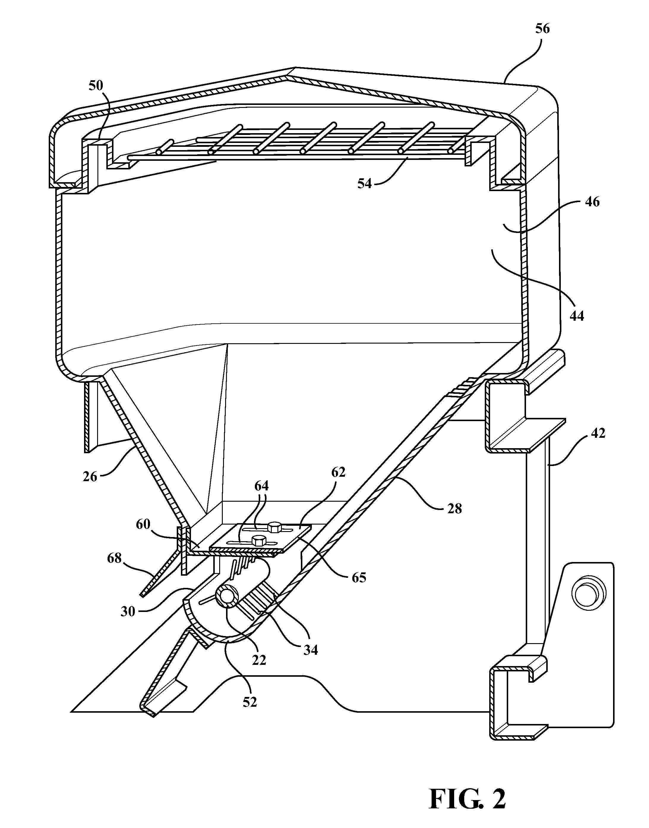
[0009]In general terms, the present invention provides a material spreader that uses a beater bar that can slowly supply small quantities of material to the discharge opening of a material spreader hopper. The beater bar has one and preferably several paddles that rotate adjacent the discharge opening and as the paddle passes the opening, discharges only the amount of material on the paddle. The present invention uses a high ratio transmission and low rpm motor to allow for extremely slow rotation of the beater bar. The motor speed can be controlled to allow very slow rotation and very small amounts of material to be discharged from the hopper.
[0012]The use of a slow rotating beater bar allows for very controlled material distribution allowing the operator to use less overall material than previously known spreader devices. The operator may then realize greater profits as less material is used to receive the desired results and the operator may better control the distribution of the material.

Problems solved by technology

One problem with these known spreaders is that they are not well suited to treat smaller surfaces.
Known spreaders over-spread material on sidewalks, since they are not readily capable of spreading smaller amounts over smaller areas.
Known spreaders will distribute too much material and will spread the material beyond the desired area.
This results in excessive material being spread, wasting resources, and material being spread over undesired areas, such as vegetation, which can be detrimental to the vegetation.

Method used


Image

  • Spreader device
  • Spreader device
  • Spreader device

Examples


Embodiment Construction

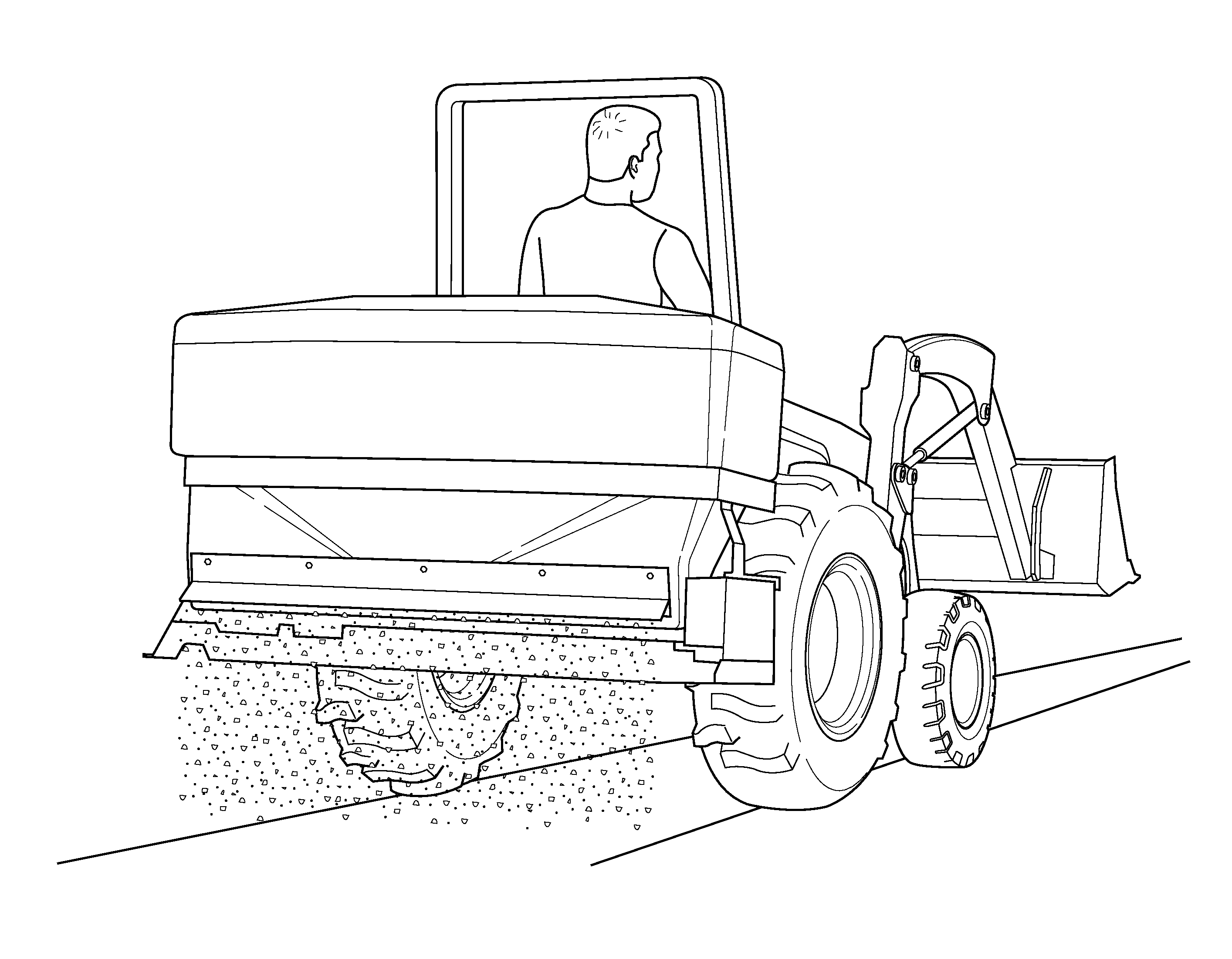
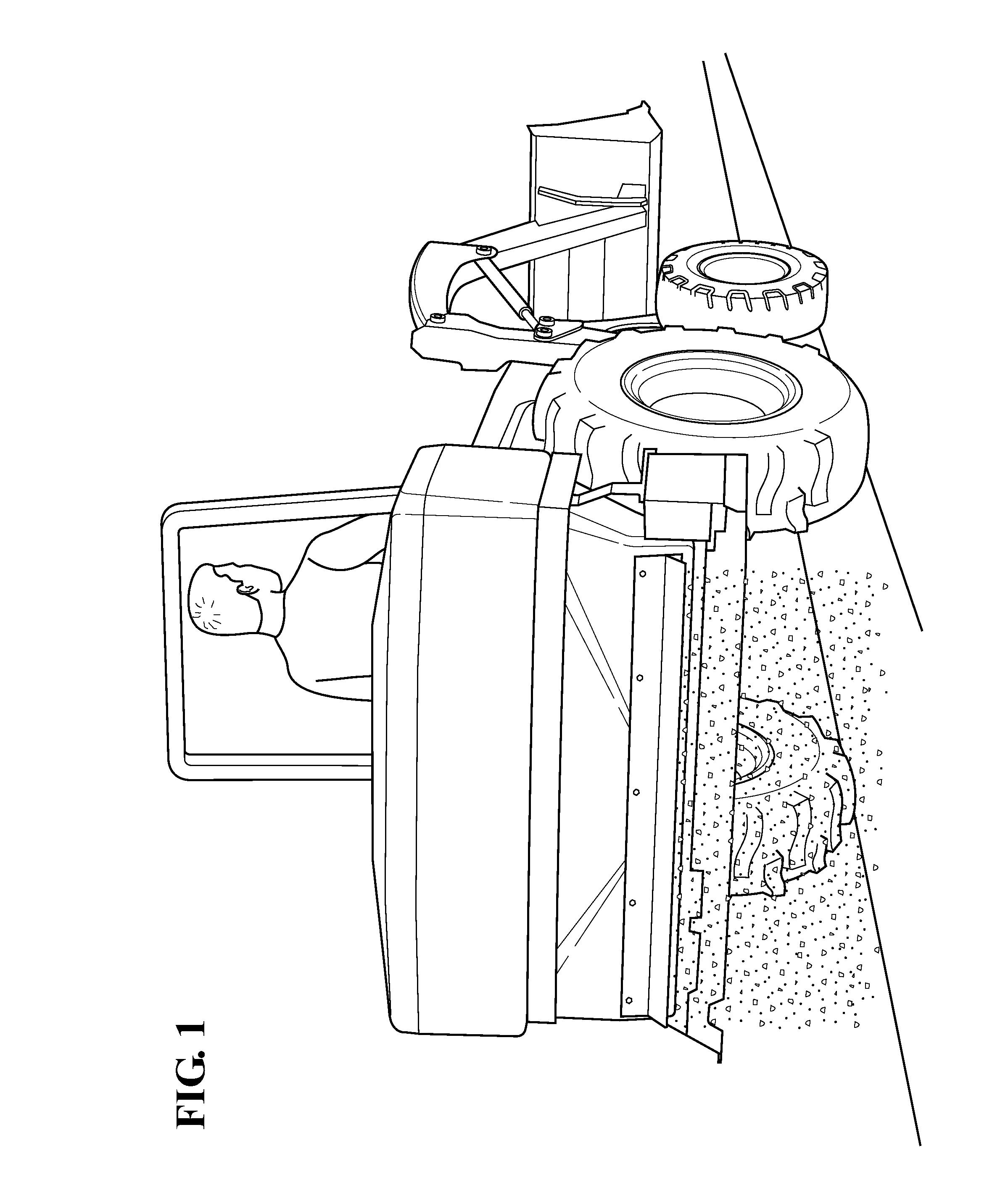
[0022]With reference to FIGS. 1, 2 and 3, the spreader device 20 of the present invention has a hopper 44 defined by a first wall 26 opposite a second wall 28 and a third wall 46 opposite a fourth wall 48, a top 50, and a bottom 52. The hopper 44 contains a surface treatment material, such as for example, salt, salt and sand mixture, sand, seed or fertilizer. It should be recognized that the term material may be used herein to include a surface treatment material, such as salt, sand, a mixture of salt, sand seed or fertilizer, or any desirable surface treatment material used for removing snow and / or ice from a surface or turf treatment. A surface may be a road, a sidewalk, a walkway, or any other surface which may have snow and / or ice or any form of turf.

[0023]The first wall 26 has an opening 30 near the bottom 52 of the hopper 44. In a first embodiment, the opening 30 extends longitudinally between the third wall 46 and the fourth wall 48, (see FIGS. 3 and 4). The opening 30 of the...


PUM


Abstract

A material spreader having a beater bar that meters the supply of small quantities of material to the discharge opening of a material spreader hopper eliminating the need for a gate. The beater bar has one and preferably several paddles that rotate adjacent the discharge opening and as the paddle passes the opening, discharges only the amount of material on the paddle. The material spreader uses a high ratio transmission and low rpm motor to allow for extremely slow rotation of the beater bar. The motor speed can be controlled to allow very slow rotation and very small amounts of material to be discharged from the hopper. The spreader does not require a gate. The discharge of material is metered electronically.

Description

RELATED APPLICATIONS[0001]This application claims benefit to provisional application No. 61 / 837,690, filed on Jun. 21, 2013, and titled Spreader Device and provisional application No. 61 / 840,056, filed Jun. 27, 2013 and titled Spreader Device.STATEMENT REGARDING FEDERALLY SPONSORED RESEARCH[0002]NONETECHNICAL FIELD[0003]This invention relates generally to material spreading devices, such as for example a salt, seed or fertilizer spreader and, more particularly, to material spreading devices using a beater bar to discharge the material from a discharge opening in the hopper of the spreader.BACKGROUND OF THE INVENTION[0004]Material spreaders are commonly used to spread salt, sand, or salt and sand mixtures over a surface to control ice and snow on the surface. There are many types of spreader assemblies, examples of such assemblies are shown in U.S. Pat. Nos. 6,089,478; D425,915; 6,422,490; and 7,347,390 all assigned to the assignee of the present application.[0005]Known spreaders hav...

Claims


Application Information

Patent Timeline
Patent Type & Authority Patents(United States)
IPC IPC(8): A01C17/00E01H10/00
CPCA01C17/003A01C17/006E01H10/007
Inventor TRUAN, CHARLESTRUAN, BARRY
Owner DOUGLAS DYNAMICS
Learn More