Vacuum

a vacuum and construction site technology, applied in the direction of vacuum cleaners, mechanical suction control, cleaning filter means, etc., can solve the problems of affecting performance, restricting airflow, and conventional vacuum systems that require regular cleaning or replacement of filters

Active Publication Date: 2016-03-01
BLACK & DECKER INC
View PDF50 Cites 13 Cited by
  • Summary
  • Abstract
  • Description
  • Claims
  • Application Information

AI Technical Summary

Problems solved by technology

Over time, however, the debris accumulates on the filter, restricting airflow and hampering performance.
Consequently, conventional vacuum systems require regular cleaning or replacement of the filter.
This is a time-intensive process that interrupts workflow.

Method used


Image

  • Vacuum
  • Vacuum
  • Vacuum

Examples


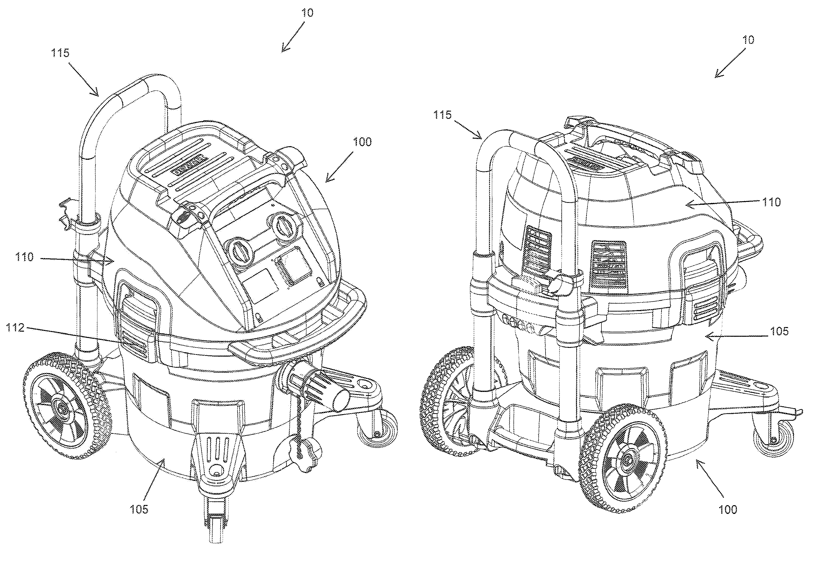
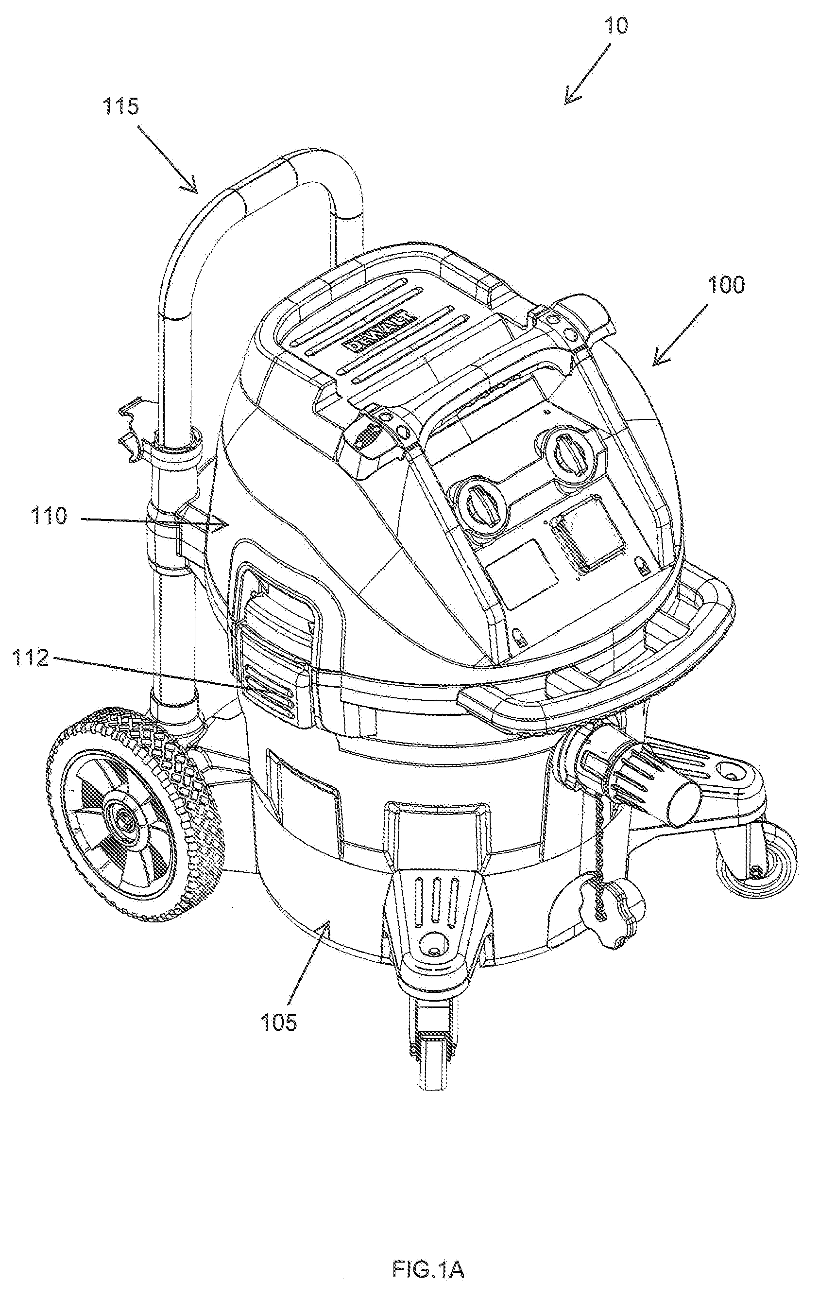
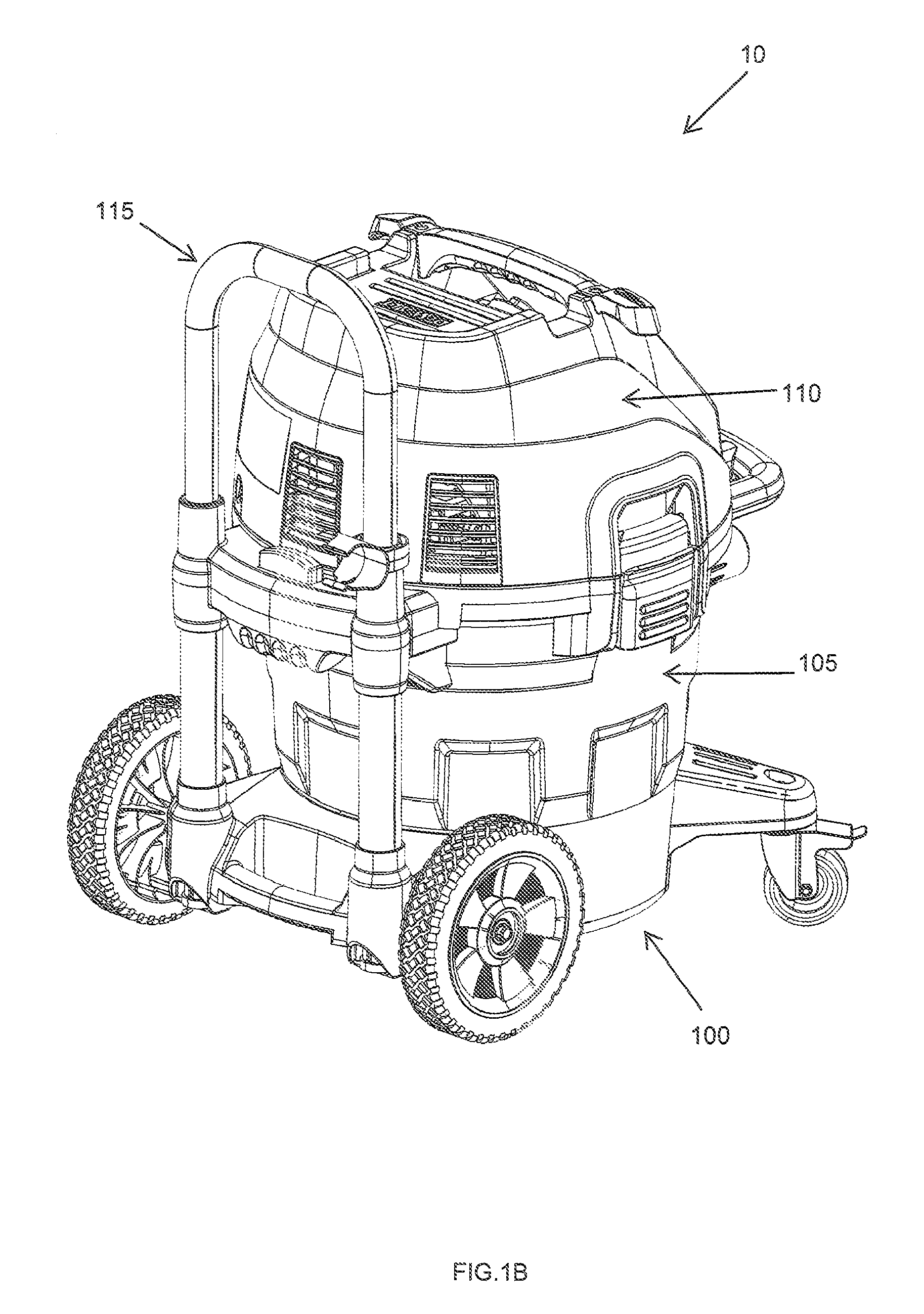
Embodiment Construction

[0053]Referring to FIGS. 1A and 1B, a vacuum system 10 in accordance with an embodiment of the invention (e.g., a wet / dry vacuum cleaner) includes a body 100 having a tank portion 105 coupled to a head or lid portion 110 via one or more latch devices 112, as well as an optional handle assembly 115. The tank 105 may possess any dimensions and shapes suitable for its described purpose. In an embodiment, the tank 105 is generally cylindrical. In another embodiment, it may possesses a generally frustoconical shape. In the embodiment illustrated in FIGS. 2A and 2B, the tank 105 includes a curved side wall 205, a closed lower end or bottom 207 and an open upper end or mouth 210. The interior surface of the tank bottom 207 may be generally concave, possessing a slightly upward curve to, e.g., prevent the tank from sagging when filled with a predetermined amount of debris. The tank mouth 210 defines a rim 212 configured to engage a corresponding shoulder forming the separator plate 900 (FIG...


PUM


Abstract

The present invention is directed to a vacuum including a dust extraction system. The system includes a filter assembly, an airflow generation assembly, and valve assembly. The airflow generation assembly is configured to draw contaminated air toward the filter assembly and exhaust filtered air as a discharge stream. The filter assembly is configured to remove contaminants from the contaminated airflow by capturing particulate material suspended within the airflow. The valve assembly is configured to selectively direct filtered airflow into the filter assembly such that the filtered air stream cleans the filter.

Description

FIELD OF THE INVENTION[0001]The present invention is directed toward a construction site or tool shop vacuum and, in particular, to a vacuum including a filter system and an airflow arrangement that periodically cleans the filter system during operation.BACKGROUND OF THE INVENTION[0002]Tool shop vacuum cleaners (e.g., wet-dry vacuums) are designed to collect debris from a work area or connected tool via suction. Such vacuums typically include a tank and motor that drives an impeller to generate an airstream within the tank. Since the airstream includes debris, care must be taken to prevent the debris from reaching the motor and causing damage. In light of this, conventional systems further include a filter positioned upstream from the motor to capture debris as the contaminated airflow passes through the tank. Over time, however, the debris accumulates on the filter, restricting airflow and hampering performance. For example, a filter initially enabling airflow of approximately 80 c...

Claims


Application Information

Patent Timeline
Patent Type & Authority Patents(United States)
IPC IPC(8): A47L5/36A47L9/00A47L9/10A47L7/00
CPCA47L5/365A47L7/0004A47L9/0072A47L9/106A47L9/009A47L9/1683A47L9/20A47L9/32
Inventor MEREDITH, DARYL, S.GRANT, JEFFREY, P.MORIN, ROBERT, R.DEMARR, DUSTIN, L.PLATO, BARRY
Owner BLACK & DECKER INC
Why Eureka
Try Eureka