Patient-specific intraluminal implants

a technology of intraluminal implants and patients, which is applied in the direction of prosthesis, instruments, blood vessels, etc., can solve the problems of affecting the use of a less invasive delivery system, the difficulty of replacing such an endoprosthesis after some years, and the proneness of structures to fixation problems, so as to achieve the effect of increasing the chan

Active Publication Date: 2016-03-15
MATERIALISE NV
View PDF10 Cites 16 Cited by
  • Summary
  • Abstract
  • Description
  • Claims
  • Application Information

AI Technical Summary

Benefits of technology

[0009]The methods described herein are envisaged to ensure that an intraluminal implant, such as but not limited to a docking structure for a functional element, will be positioned in the optimal location in the patient's lumen. This implies positioning of the implant in an anatomical location conform to the patient's anatomy (lumen), but also in an anatomical area or zone that is stable in terms of its motion in time. To this end, the intraluminal implants are provided with an outer surface which is configured to comprise patient-specific anatomy engagement surfaces or contact points corresponding to specifically selected anatomical regions of the lumen wall. In this way, the implant can be nested stably against a specific region of the lumen wall of the patient, and has an increased chance of being maintained in this position.
[0022]identifying for said patient, the anatomical regions in the anatomical area of said heart valve showing greater stability in time;

Problems solved by technology

However, in some surgical cases the use of a less invasive delivery system is hindered by form, size and material of the intraluminal endoprostheses.
When there are no minimally invasive endoprostheses available, a major surgical intervention is required and while this can often be conducted for the majority of the patients, the replacement of such an endoprosthesis after some years is more difficult due to the aging of the patient.
However, similar to the functional intraluminal endoprostheses, these types of structures are also prone to fixation problems as the position of the docking structure is highly unstable.

Method used


Image

  • Patient-specific intraluminal implants
  • Patient-specific intraluminal implants
  • Patient-specific intraluminal implants

Examples


examples

Identification of Suitable Locations for Use in the Development of a Patient-Specific Intraluminal Implant

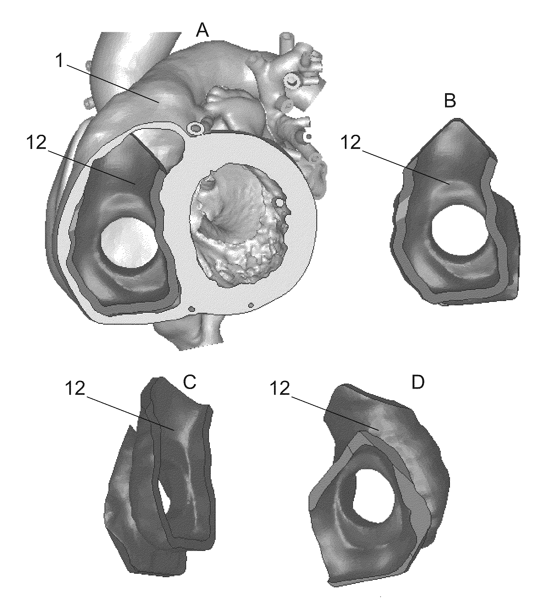
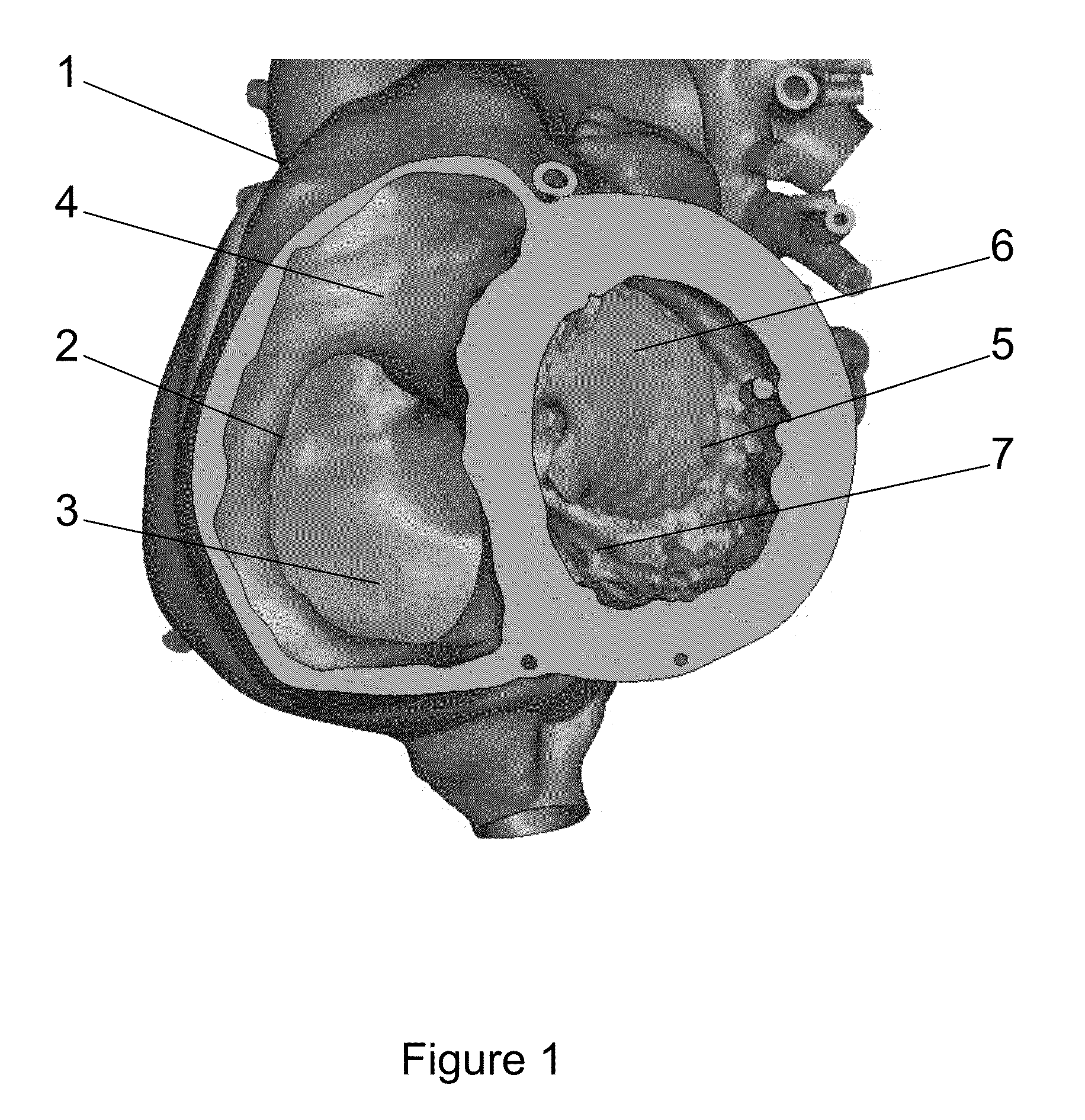
[0124]The present example provides a particular embodiment which may be used to identifying and selecting the locations in a patient's anatomy that are suitable for use as a base for the patient-specific contact surfaces of a intraluminal implant, such as but not limited to, an intraluminal docking structure.

[0125]In first instance the patient's anatomy onto which the intraluminal docking structure needs to be deployed is identified (e.g. the tricuspid valve a shown in FIG. 1). Using medical imaging equipment the variation of the anatomy of tricuspid valve is monitored in function of time. For this purpose a plane is identified in which the measurements are performed (FIG. 3), thereby providing cross section images (FIG. 4) of the plane cut in function of time. From these images specific parameters are measured such as for instance the maximum distance within the intersection of...


PUM

PropertyMeasurementUnit
displacementaaaaaaaaaa
diameteraaaaaaaaaa
diameteraaaaaaaaaa

Abstract

Methods are provided for generating intraluminal prosthetic implants designed to fit onto specific anatomical locations within regions which are stable in terms of their motion in time.

Description

CROSS-REFERENCE TO RELATED APPLICATION[0001]This application claims priority to European Patent Application No. 12185324.6, filed Sep. 21, 2012, the contents of which are incorporated herein by reference in their entirety.FIELD OF THE INVENTION[0002]Methods are provided for generating intraluminal implants which contain structural information that conforms to patient specific anatomical regions to ensure an optimal fit.BACKGROUND[0003]Endoprostheses are a commonly used way of dealing with diseases in interventional medicine and surgery. Mesh-based endoprostheses such as stents, stent grafts, heart valve frames, etc. are of particular importance in cardiovascular applications. Other fields of medicine also make use of such endoprostheses, e.g. pulmonary tract stents, oesophagus stents, etc.[0004]Intraluminal endoprostheses such as stents are typically designed such that they are deployable by catheter or similar stent delivery system, as it is desirable for stent placement procedures...

Claims


Application Information

Patent Timeline
Patent Type & Authority Patents(United States)
IPC IPC(8): A61F2/24A61F2/30G06T19/20
CPCA61F2/30942A61F2/2418G06T19/20A61F2240/002A61F2250/006G06T2210/41G06T2219/2021Y10T29/49A61B2034/108B33Y80/00A61F2210/0004A61F2220/0016A61F2250/0067A61F2/07A61F2/2409
Inventor ROELS, TOONVERSCHUEREN, PETER
Owner MATERIALISE NV
Why Eureka
Try Eureka