
Vehicle behavior control apparatus

a technology of behavior control and vehicle, which is applied in the direction of control devices, resilient suspensions, interconnection systems, etc., can solve the problems that the intended behavior and stability of the body cannot be acquired

Active Publication Date: 2016-03-15
TOYOTA JIDOSHA KK
View PDF24 Cites 1 Cited by
  • Summary
  • Abstract
  • Description
  • Claims
  • Application Information

AI Technical Summary

Benefits of technology

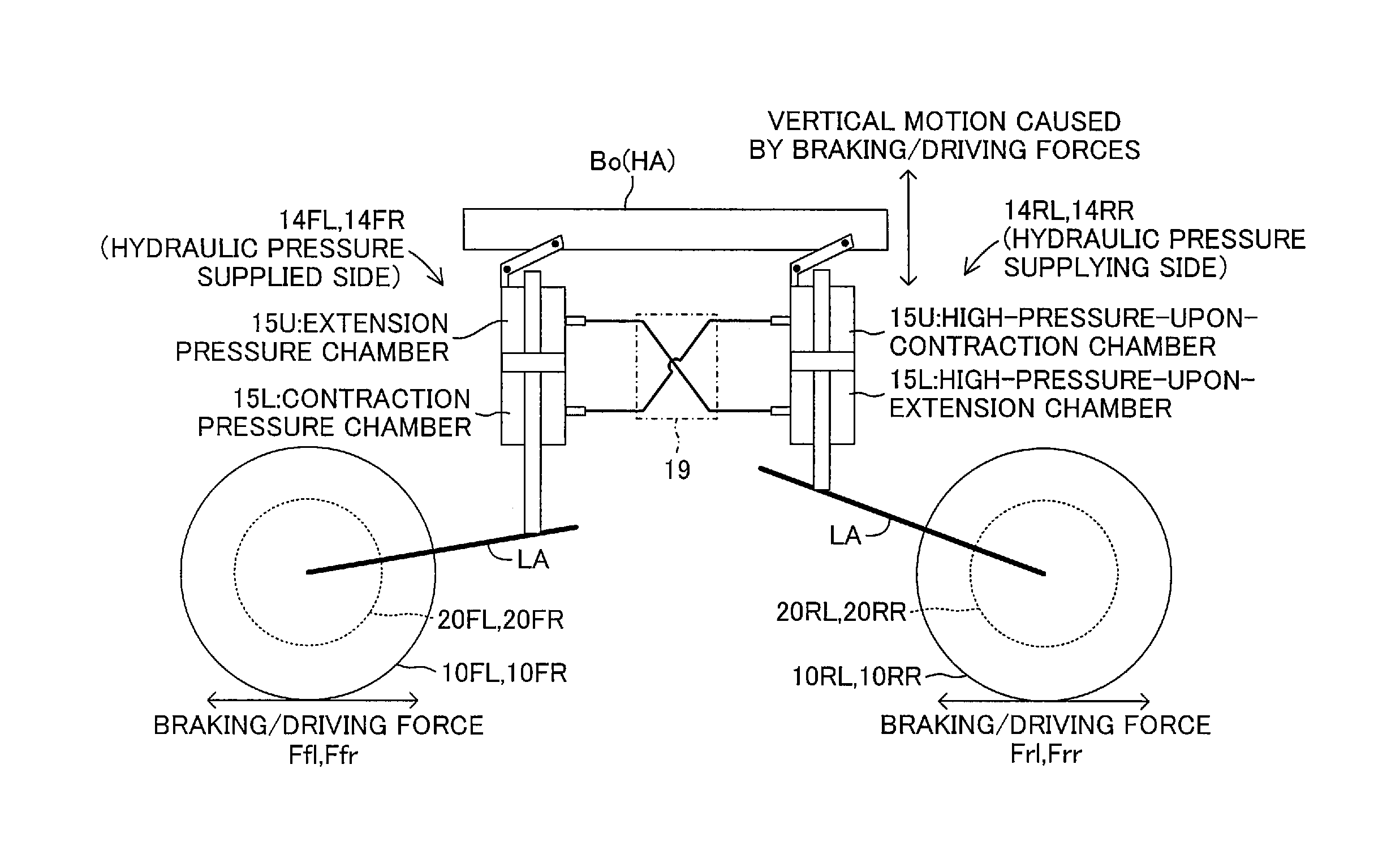
[0018]With this configuration, for example, in a case where the vertical force acting on the body as the component force of the predetermined driving force or braking force generated on the wheel by the braking / driving force generation mechanism increases owing to a difference in suspension geometry in the suspension mechanism, the fluid pressure cylinder on the fluid pressure supplying side arranged on the side having a margin in the vertical force for controlling the behavior generated on the body can convert the vertical force (in other words, translational force) acting on the body into the fluid pressure to supply the fluid pressure cylinder on the fluid pressure supplied side with the fluid pressure. In other words, for example, in a case where the vertical force acting on the body as the component force of the predetermined driving force or braking force generated on the wheel by the braking / driving force generation mechanism decreases owing to the difference in suspension geometry in the suspension mechanism, the fluid pressure cylinder on the fluid pressure supplying side can supply the converted fluid pressure to the fluid pressure cylinder on the fluid pressure supplied side arranged on the side insufficient in the vertical force (side not having a margin in the vertical force) for controlling the behavior generated on the body.
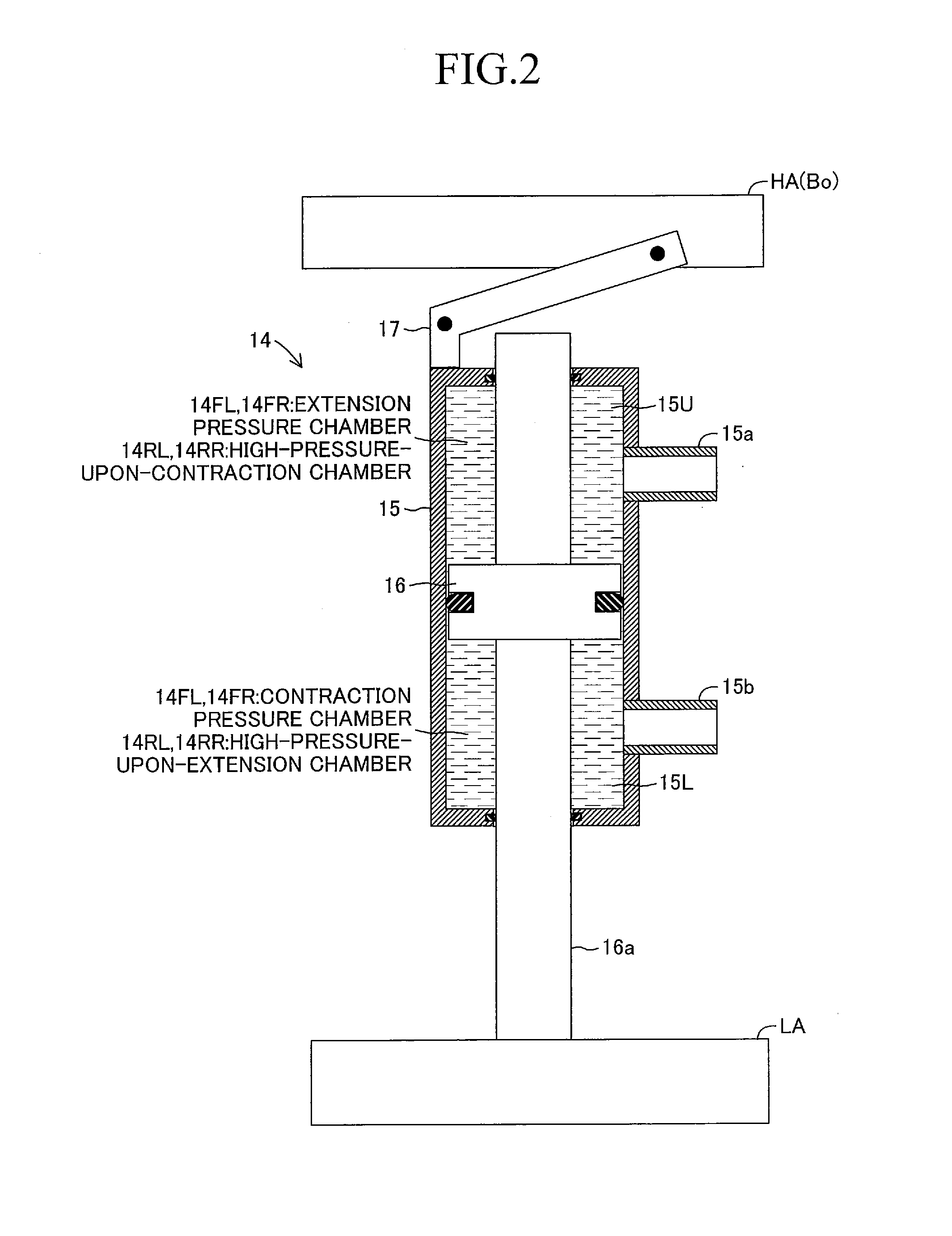
[0035]As a result of the employment of the various connection forms, the high-pressure-upon-extension chamber or the high-pressure-upon-contraction chamber of the fluid pressure cylinder on the fluid pressure supplying side and the extension pressure chamber or the contraction pressure chamber of the fluid pressure cylinder on the fluid pressure supplied side can be appropriately selected to be connected to each other depending on a pitch behavior, a heave behavior, and a roll behavior as the behaviors generated on the body. Thus, the pitch behavior, the heave behavior, and the roll behavior generated on the body can be more efficiently and more surely be controlled.

Problems solved by technology

Therefore, intended behavior and stability of the body may not be acquired by controlling only the driving forces or braking forces generated on the respective wheels.

Method used


Image

  • Vehicle behavior control apparatus
  • Vehicle behavior control apparatus
  • Vehicle behavior control apparatus

Examples


Embodiment Construction

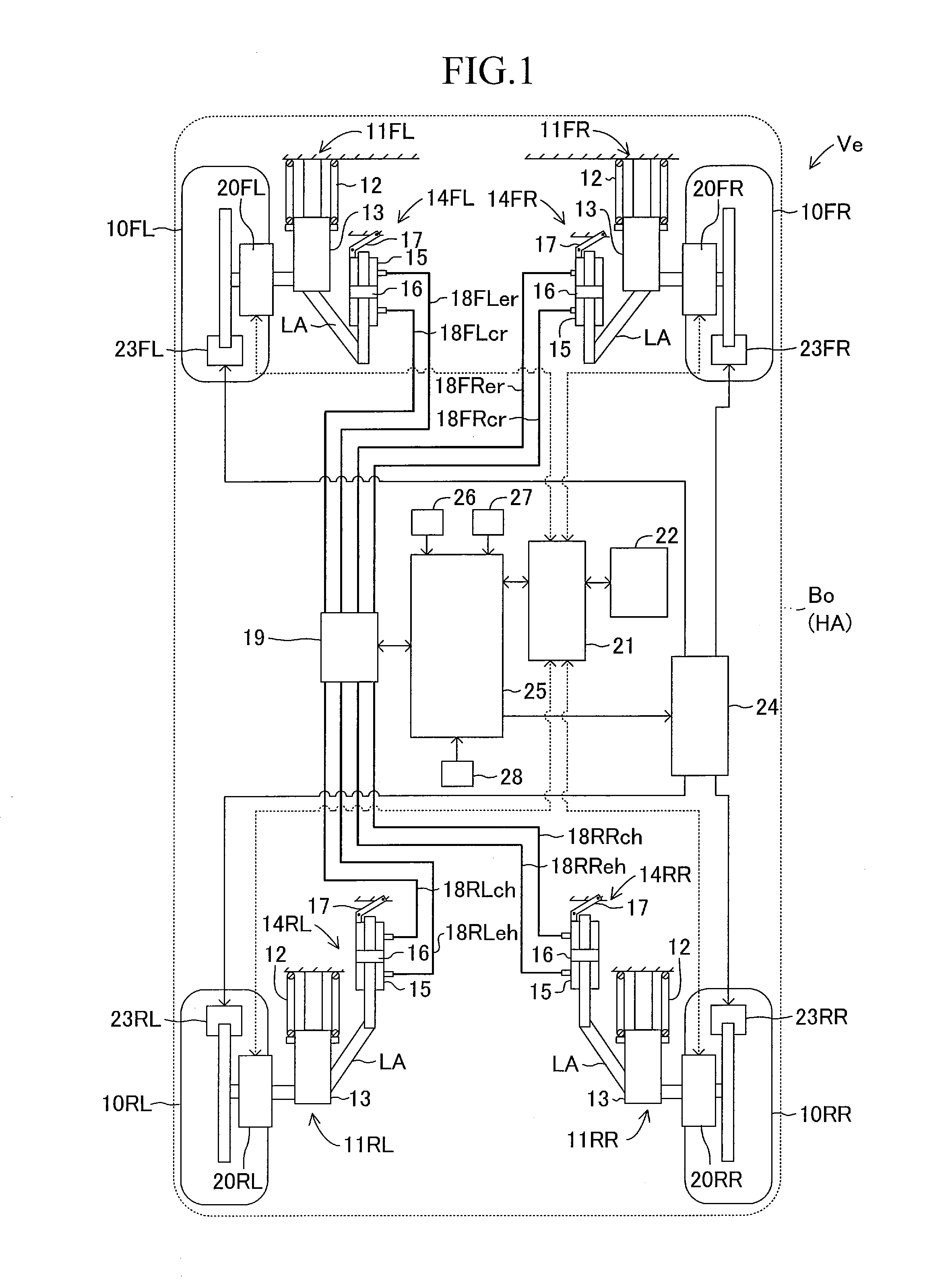
[0050]A detailed description is now given of a vehicle behavior control apparatus according to an embodiment of the present invention referring to the drawings. FIG. 1 schematically illustrates a configuration of a vehicle Ve on which the vehicle behavior control apparatus according to this embodiment is installed.

[0051]The vehicle Ve includes front left and right wheels 10FL and 10FR and rear left and right wheels 10RL and 10RR constructing an unsprung member LA. Then, the front left and right wheels 10FL and 10FR are respectively independently supported via suspension mechanisms 11FL and 11FR by a body Bo constructing a sprung member HA of the vehicle Ve. Moreover, the rear left and right wheels 10RL and 10RR are respectively independently supported via suspension mechanisms 11RL and 11RR by the body Bo (sprung member HA) of the vehicle Ve. The front left and right wheels 10FL and 10FR and the rear left and right wheels 10RL and 10RR are the same in configuration, and thus are her...


PUM


Abstract

In order to control a behavior generated on a body as a result of a travel of a vehicle, an electronic control unit controls rotation of each of in-wheel motors, thereby generating a predetermined braking force or driving force approximately the same in magnitude on each wheel. Meanwhile, the electronic control unit uses respective pipelines and a direction control circuit depending on the behavior generated on the body to connect fluid pressure cylinders on a fluid pressure supplying side and fluid pressure cylinders on a fluid pressure supplied side to each other for communication. As a result, the fluid pressure cylinders convert vertical forces of the body acting as component forces of a predetermined braking / driving force into hydraulic pressures and supply the fluid pressure cylinders with the hydraulic pressures, and the fluid pressure cylinders convert the supplied hydraulic pressures into vertical forces, thereby exerting the vertical forces on the body.

Description

TECHNICAL FIELD[0001]The present invention relates to a vehicle behavior control apparatus for independently controlling a driving force or a braking force to be generated on each of wheels of a vehicle depending on a behavior generated on a body of the vehicle.BACKGROUND ART[0002]In recent years, as a form of an electric vehicle, there has been developed a vehicle of so-called in-wheel motor type including a motor arranged inside or in a neighborhood of a wheel forming an unsprung member of the vehicle and using the motor to directly drive the wheel. On the vehicle of in-wheel motor type, a driving force or a braking force imparted to each wheel can individually be controlled depending on a travel condition of the vehicle by independently controlling rotation of the motor provided to each wheel, in other words, independently controlling driving (power running) or regeneration of each motor.[0003]Regarding the vehicle of the in-wheel motor type, for example, in Patent Literature 1, ...

Claims


Application Information

Patent Timeline
Patent Type & Authority Patents(United States)
IPC IPC(8): B60W10/22B60G17/06B60G17/02B60G21/10B60W30/02B60W30/04B60W10/192B60W10/08B60G17/016B60G17/0195
CPCB60W30/025B60G17/0195B60G17/02B60G17/06B60W10/08B60W10/192B60W10/22B60W30/04B60G2204/182B60W2030/043B60K7/0007B60W10/184B60W30/045B60W2520/403B60W2520/406B60W2720/403B60W2720/406B60W2710/226
Inventor NAKATSU, MASATOSHI
Owner TOYOTA JIDOSHA KK
Learn More