Ellipsoidal V-hull

a v-shaped, ellipsoidal technology, applied in the direction of hulls, waterborne vessels, vessel construction, etc., can solve the problems of narrow bow area, rough ride, and inability to operate at the higher speed of a planing hull, so as to achieve good fuel economy and maneuverability, improve load carrying capacity at speed, and improve comfort

Active Publication Date: 2016-03-15
RICKBORN CHRISTOPHER +1
View PDF10 Cites 3 Cited by
  • Summary
  • Abstract
  • Description
  • Claims
  • Application Information

AI Technical Summary

Benefits of technology

[0016]Accordingly, the primary object of the present invention is to provide a boat hull that provides a smooth ride at both high and low speeds with good fuel economy and maneuverability. Another objective is to provide better load carrying capacity at speed and greater comfort (less rolling motion) when stationary in waves.
[0017]In one embodiment a modified hull design combines features found on various hull designs. The forward region of the hull may have a bulbous, i.e. ellipsiodal, shape from which an ellipsiodal shaped keel may extend toward the stern. Chines, strakes and spoilers may by combined to reduce drag at lower and higher speeds typical of a flatbottom hull or a deep V hull while also having ride comfort better that that of a deep hull boat at higher speeds in waves. Lifting strakes, or spoilers, may also contribute to reduce drag. An aft centerline pad may also be incorporated into the hull design.

Problems solved by technology

Characteristically, however, the flat, broad bow area creates a rough ride.
These boats are usually limited to low horsepower motors because they do not generally handle well at high speed.
“Displacement” hulls push through or cruise through the water instead of skimming on the surface and are not able to operate at the higher speeds of a planing hull.
At slow speeds they are more efficient than Planing hulls but not as efficient as Displacement hulls, while at medium speed they are more efficient than both Displacement and Planing hulls.
Semi Displacement hulls are not usually able to operate at the high speeds typical of Planing hulls but are able to operate efficiently at higher speeds than a Displacement hull.
However, at low speed a deep V hull is very inefficient.
Furthermore, at low speeds, a deep V hull is less stable, less maneuverable and tends to roll side to side to a high degree when side on to the waves.

Method used


Image

  • Ellipsoidal V-hull
  • Ellipsoidal V-hull
  • Ellipsoidal V-hull

Examples


Embodiment Construction

[0027]Before explaining at least one embodiment of the invention in detail, it is to be understood that the invention is not limited in its application to the details of construction and to the arrangements of the components set forth in the following description or illustrated in the drawings. The invention is capable of other embodiments and of being practiced and carried out in various ways. Also, it is to be understood that the phraseology and terminology employed herein are for the purpose of description and should not be regarded as limiting.

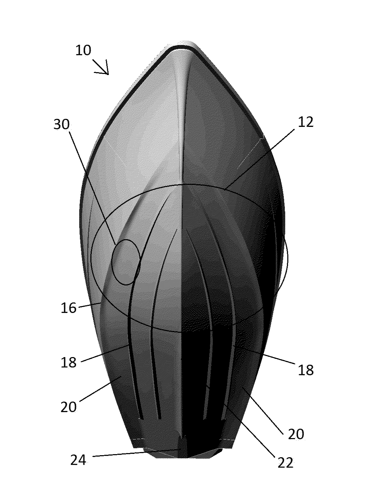
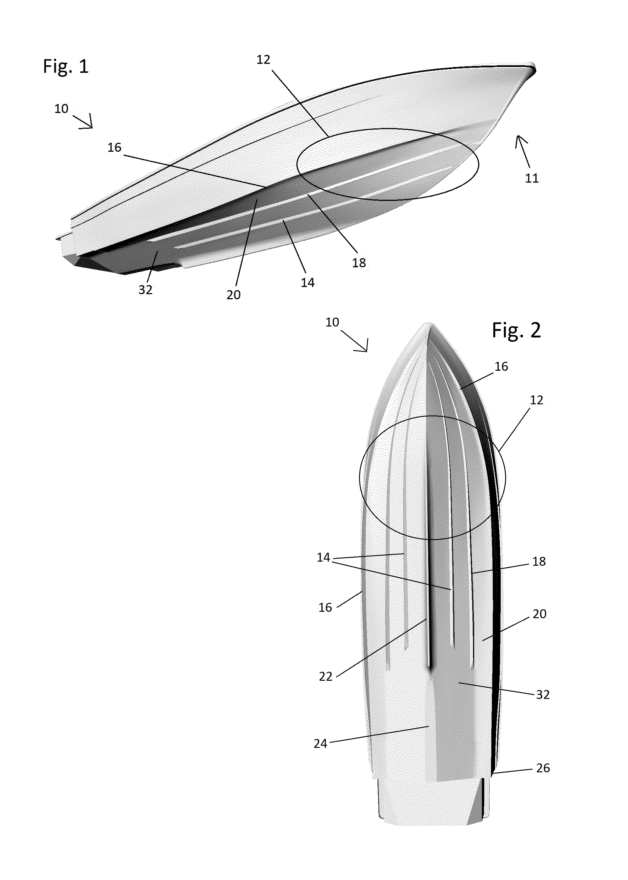
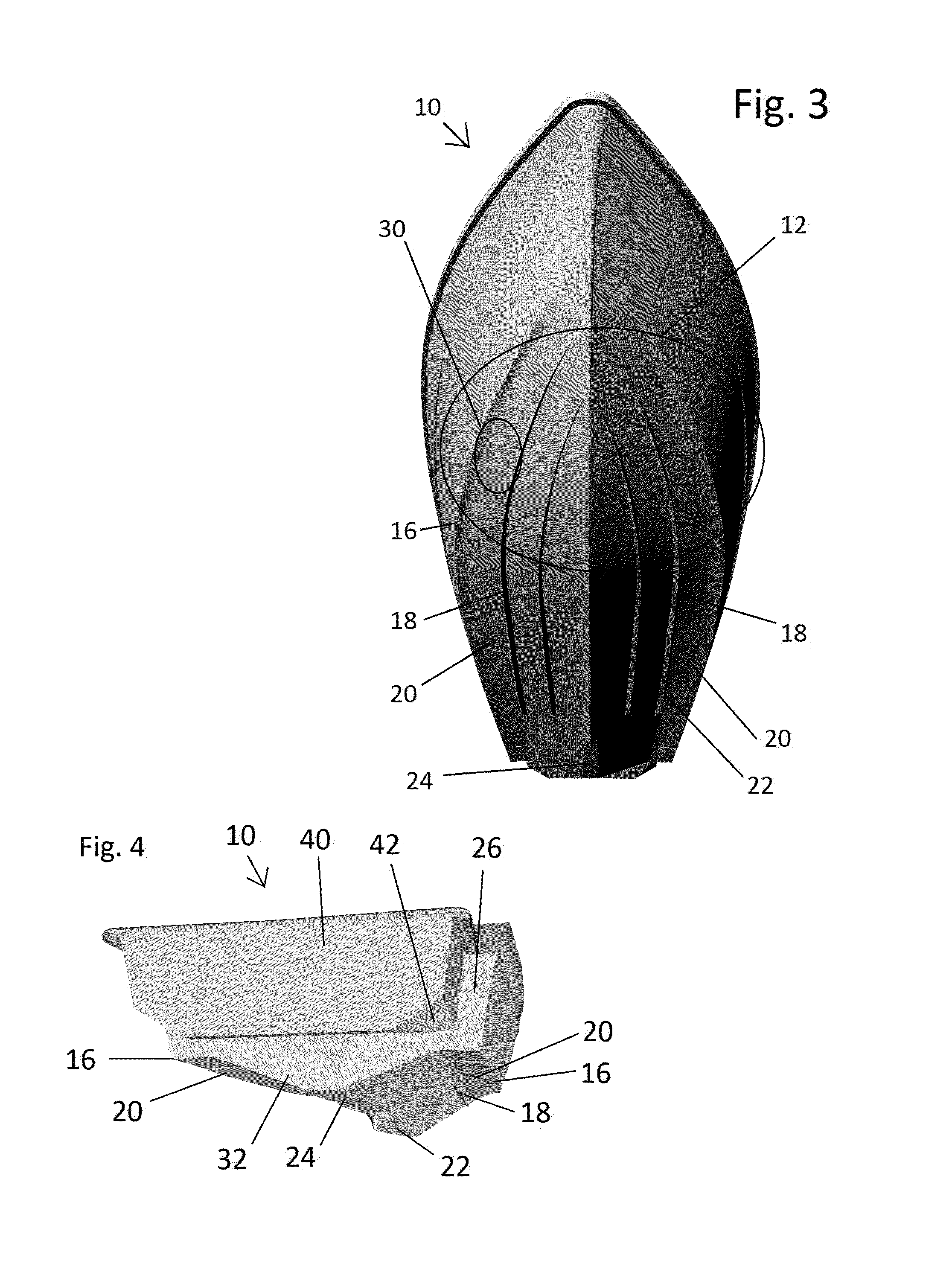
[0028]Disclosed is a hull design that combines features found on various different hull designs. The forward region of the hull may have a bulbous, i.e. ellipsiodal, shape from which an ellipsiodal shaped keel may extend toward the stern. Modified chines and strakes may by combined to reduce drag at lower speeds typical of a flatbottom boat while also having the stability of a deep hull boat at higher speeds. Lifting strakes, or spoilers, ...


PUM

PropertyMeasurementUnit
lengthaaaaaaaaaa
deadrise angleaaaaaaaaaa
widthaaaaaaaaaa

Abstract

An improved boat hull design includes a region of ellipsiodal fullness in the forward portion of the hull, ellipsiodal curvature over the remainder of the hull, a chine with a chine flat with an increasing width as it approaches the stern and one or more strakes. One of the strakes is located where the chine flat meets the V portion of the hull. The hull provides stability and a smooth ride at both high and low speeds in smooth and rough water and is highly maneuverable. The hull also has good weight carrying ability at speed while not requiring excessive power. The hull minimizes rolling when stationary or at low speed in waves.

Description

BACKGROUND OF THE INVENTION[0001]1. Field of Endeavor[0002]The present invention relates to apparatuses, systems and methods for improved boat of both mono-hull and multi-hull designs. More particularly, the invention relates to boat hulls modified to provide better fuel economy, maneuverability, a smoother ride at both high and low speeds, less side to side rolling motion when stationary in waves and greater weight carrying capacity.[0003]2. Background Information[0004]Boat hull design has been a constantly evolving field of art for thousands of years. In particular, the development of non-wind propulsion systems, material science and other technologies, has contributed to many advances in hull design over the past two hundred years.[0005]Flat-bottom boats have a large, substantially flat hull bottom, making them very stable in calm weather. Characteristically, however, the flat, broad bow area creates a rough ride. These boats are usually limited to low horsepower motors because t...

Claims


Application Information

Patent Timeline
Patent Type & Authority Patents(United States)
IPC IPC(8): B63B5/24B63B1/20B63B3/14B63B3/38B63B1/04
CPCB63B5/24B63B1/20B63B3/14B63B1/042B63B3/38B63B2001/201
Inventor RICKBORN, CHRISTOPHERRICKBORN, SPENCER
Owner RICKBORN CHRISTOPHER
Why Eureka
Try Eureka