

X-ray inspection using wavelength-shifting fiber-coupled scintillation detectors
a scintillation detector and wavelength-shifting technology, applied in the field of fiber-coupled scintillation detectors, can solve the problems of inherently low light collection efficiency of conventional backscatter detectors, noise limit of imaging systems, and different detection requirements of x-ray backscatter inspection systems
- Summary
- Abstract
- Description
- Claims
- Application Information
AI Technical Summary
Benefits of technology
Problems solved by technology
Method used
Image

Examples
Embodiment Construction
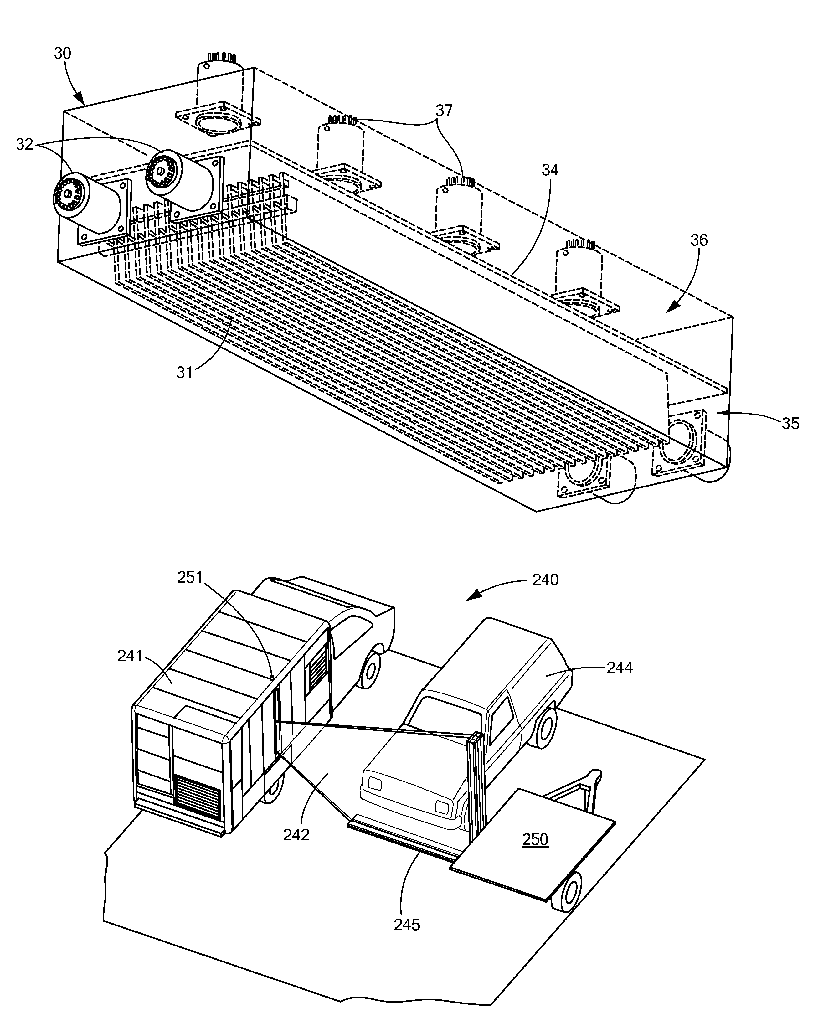
[0012]In accordance with various embodiments of the present invention, systems and methods are provided that apply fiber-coupled scintillation detectors to problems in backscatter and transmission x-ray inspection.
[0013]For convenience of notation, a wavelength-shifted fiber-coupled scintillation detector may be referred to herein as an “Sc-WSF” detector.
[0014]In a first embodiment of the present invention, a detector of penetrating radiation is provided that has an unpixelated volume of scintillation medium for converting energy of incident penetrating radiation into scintillation light. The detector has multiple optical waveguides, aligned substantially parallel to each other over a scintillation light extraction region that is contiguous with the unpixelated volume of the scintillation medium, The optical waveguides guide light derived from the scintillation light to a photo-detector for detecting photons guided by the waveguides and for generating a detector signal.
[0015]In othe...
PUM
 Abstract
Description
Claims
Application Information